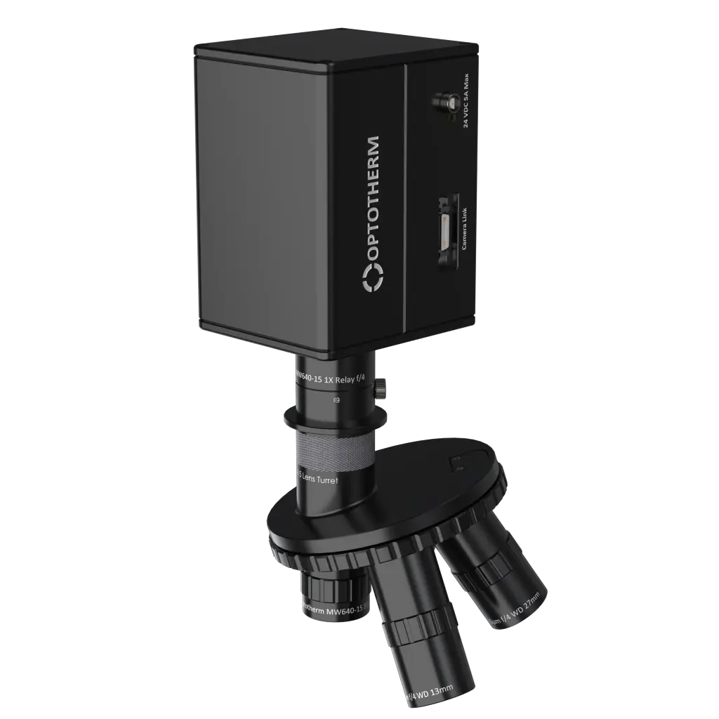
MW640-15 Camera (3.7-4.8µm)
PN0773 The MW640-15 is Optotherm’s most sensitive thermal imaging camera, providing spatial resolution down to 2μm and captures images at 100Hz. Due to the camera’s high image capture rate, lock-in tests can be performed with test frequencies up to 25Hz, reducing thermal diffusion and improving fault location. Because silicon is partially transparent in the MWIR range, features and metallization can be observed when testing devices from the backside. The MW640-15 camera also provides the ability to see through window materials commonly used in chip testing, such as silicon carbide.
Applications
- Semiconductor device failure analysis
- Circuit board failure analysis
- Backside analysis through partially transparent silicon
- Microscopic temperature measurement and analysis of features down to 2µm in size
Overview
Primary advantages of MWIR over LWIR for Lock-in Testing:
1. Higher spatial resolution of 2µm/pixel versus 5µm/pixel for LWIR due to short working wavelength and diffraction limit of lens design.
2. Higher transmission of Silicon (~50%) between 3-5µm allows viewing semiconductor features through Silicon.
3. Higher detector sensitivity reduces lock-in test time and allows detection of lower-power faults.
4. Higher camera frame rate improves lock-in test sensitivity and allows lock-in testing at higher cycle frequencies to isolate faults on thin devices.
Stirling Cooler Technology
The MWIR camera is cooled by a mechanical Stirling cooler which cools the detector to -190°C. Stirling coolers have a limited life span with an MTTF (mean time to failure) of ~10,000 hours. Optotherm chose MCT over InSb primarily for lower cooling requirements resulting in reduced dewar cooler weight, power requirements, and therefore reduced support issues.
Comprehensive Calibration
Each camera undergoes a rigorous calibration procedure to precisely correlate detector response to temperature measurement.
Included Components
- Mid-wavelength radiometric infrared camera
- Shock resistant carrying case
- 5m CameraLink Cable MDR to SDR (unpowered) cable for MW640-15
Required Products
- [PN0177] Thermalyze Image Analysis Software
- MW640-15 Relay Lens
- At least one MW640-15 compatible lens (see in specifications below)
Related Products
Specifications
|
Camera |
[PN0773] MW640-15 MWIR Camera, 100Hz |
| Compatible lenses | PN0778 MW640-15 2 Micron Objective Lens PN0777 MW640-15 5 Micron Objective Lens PN0776 MW640-15 20 Micron Objective Lens PN0775 MW640-15 80 Micron Objective Lens |
Detector
|
Sensor Technology |
Photovoltaic Mercury Cadmium Telluride (HgCdTe / MCT) |
|
Cryogenic Cooler |
Stirling cycle micro-cooler (0.5 W) |
|
Dewar |
Vacuum sealed metal (MTTF > 10,000 hours) |
|
Cold Shield |
F4 |
|
Sensor Pitch |
15 µm |
|
NETD |
< 25 mK |
|
Sensor Size |
640 x 512 |
|
Sensor Wavelength |
3.7 – 4.8 µm (3700-4800 nm) |
* Noise Equivalent Temperature Difference (NETD) specifies the smallest temperature difference that can be detected. The value stated is NETD at 100 Hz frame rate.
Camera Design
| Detector Thermal Mount | Thermal pad to copper heat sink |
| Circuit Board Set |
Custom separated "L" set |
|
Detector Bias Board |
High precision resistors |
| Status Light | LED status light |
Camera Control and Image Output
|
Frame Rate |
100 Hz (1,000 Hz with 160 x 120 windowing) |
|
Video Transfer |
Camera Link |
|
Camera Control |
Camera Link UART |
Time to First Image |
† Optotherm thermal imaging cameras with frame rate of 9Hz or lower may be exported to many countries without an export license under ECCN 6A993.a NLR (no license required).
‡ Camera models using Camera Link are only compatible with Windows 10 Operating System. Camera models using USB are compatible with both Windows 10 and Windows 11 Operating System.
Power
|
Power |
24VDC (5A max) |
Power Consumption |
Physical
Ambient Operating Range | |
Ambient Storage | |
|
Camera Dimensions
|
162 x 110 x 120mm (l x w x h)
|
|
Camera Weight |
3kg |
Camera Mounting | 5 x M6 on 25 mm centers |
|
Lens Connection |
|
| Moving Parts |
|
Setup
Mounting Threads
- When mounting the camera, make sure bolts are securely screwed into the camera’s internal threads to prevent the possibility of dropping or damaging the camera. There are five M6 internal threads (25 mm apart) on the bottom of the camera that can be used for mounting the camera (see Figure 1).
Camera Damage: The MW640-15 camera is a delicate precision optical instrument and should be handled with care.
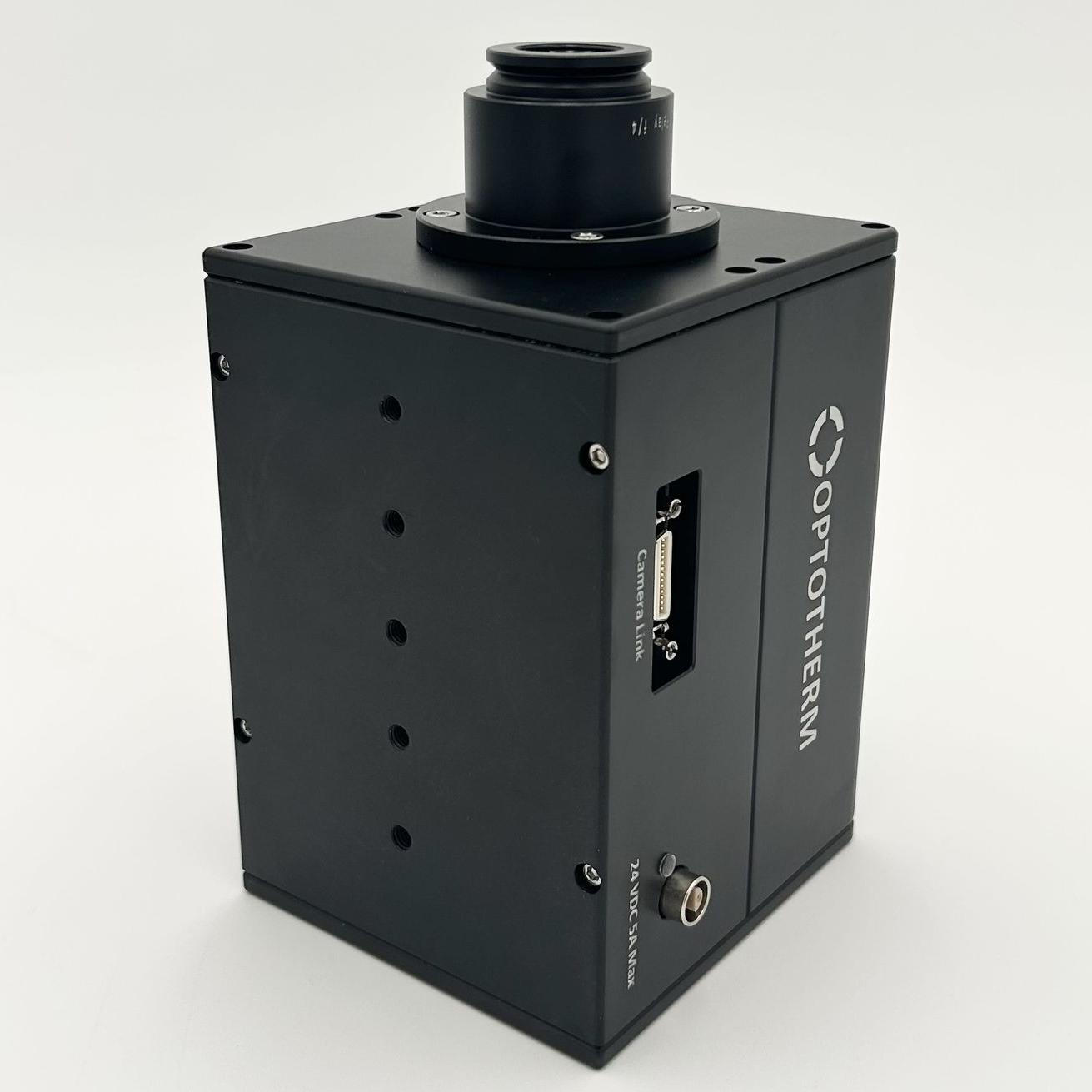
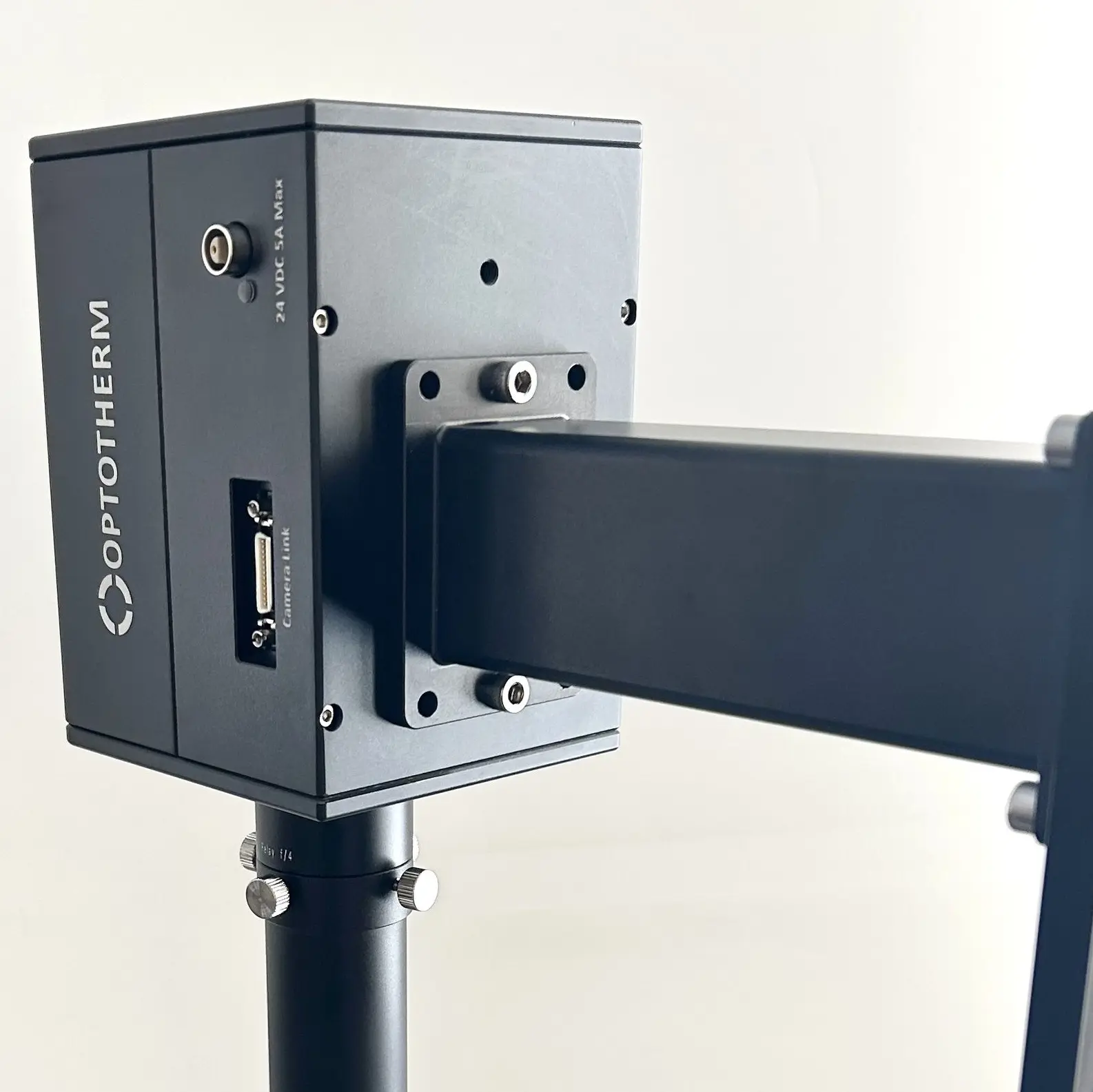
Figure 1: M6 threaded holes on bottom of camera
Figure 2: Camera mounted to PN1035 MW640-15 Mounting Arm with (x2) M6 socket screws
USB3 Cable (see Camera Link Cable Setup for retired IS640 cameras)
- Insert the small connector end of the USB3 cable to the USB3 receptacle on the back of the camera (see Figure 2) and tighten the thumbscrews (see Figure 3).
- Insert the other end of the USB3 cable into a USB port on the back of your computer.
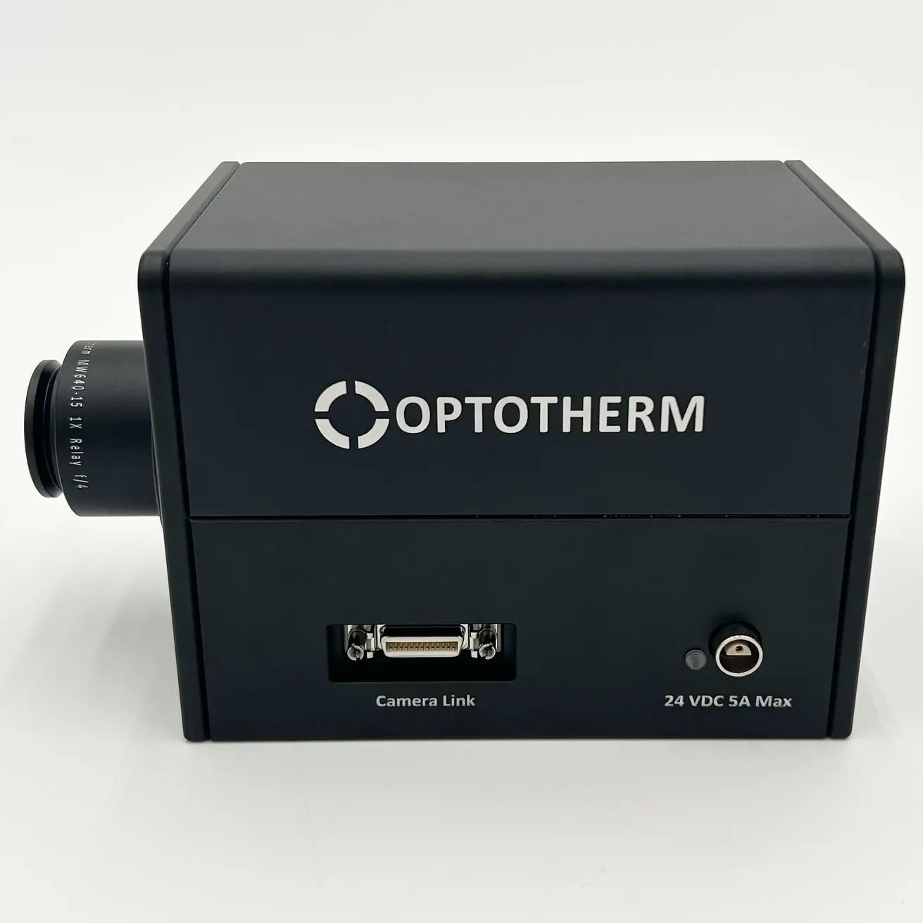
Figure 3: Camera Link receptacle and 24VDC 5A Power receptacle
Single Lens Adapter
The Single Lens Adapter or 4 Position Turret can be secured to the c-mount on the Relay Lens using (x4) thumbscrews.
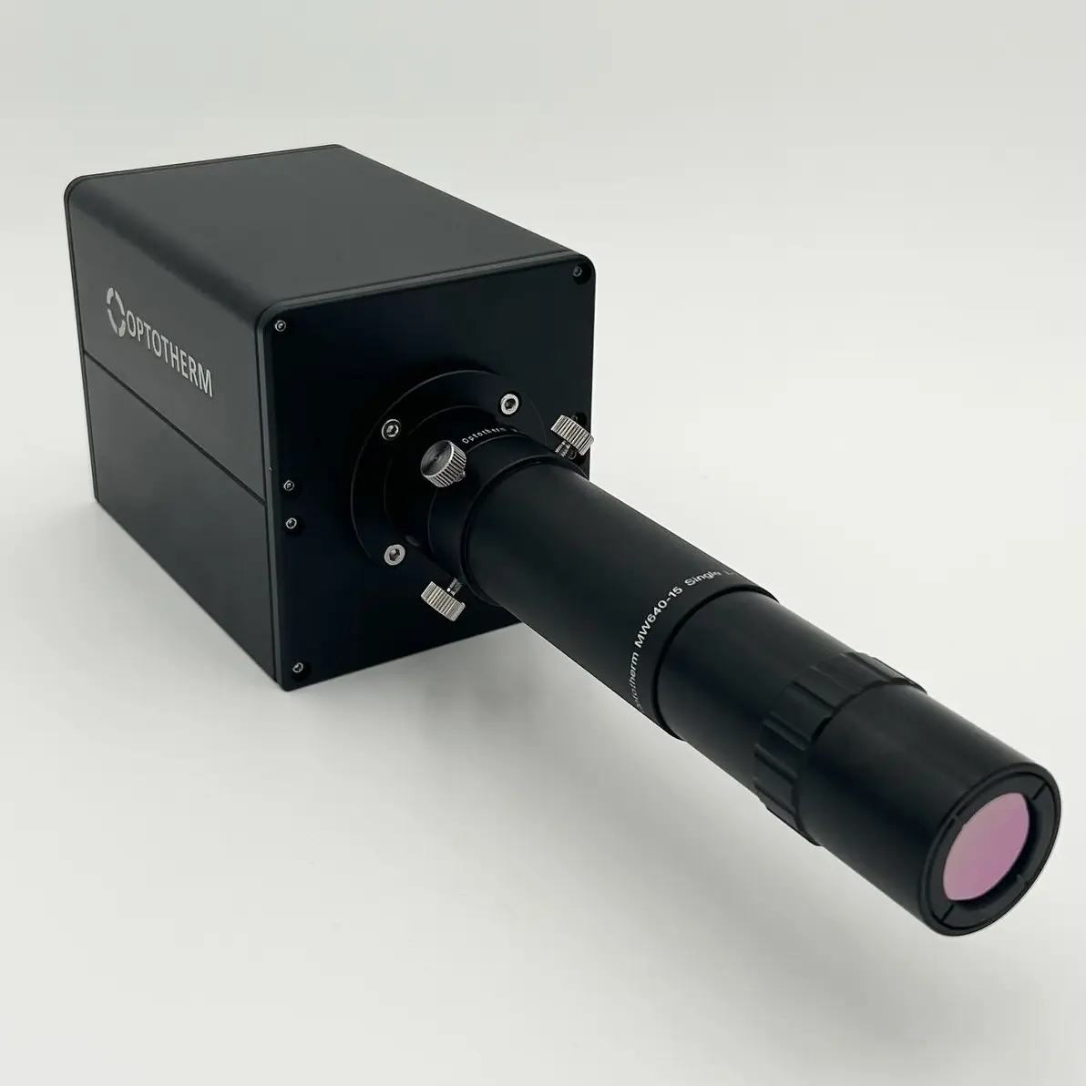
Figure 4: Single Lens Adapter secured with (x4) thumbscrews onto Relay Lens.
Figure 5: Turret secured with (x4) thumbscrews onto Relay Lens.
Camera Environment
Ambient Environment
Optotherm cameras are intended to be operated indoors. Rapid temperature changes can reduce the camera’s measurement accuracy. After handling the camera and after exposing the camera to a different ambient environment, allow the camera temperature to stabilize before performing tests that require high accuracy. The larger the temperature change, the more time will be required for the camera to stabilize.
To prevent rapid temperature changes, avoid mounting the camera in direct sunlight, close to heat sources, in front of air vents, or next to open doors or windows. To minimize the time required for stabilization, avoid transporting or storing the camera in extreme temperature environments.
Camera Orientation
The camera can be operated in any orientation; aimed up, down, sideways, or at any angle. When the camera is mounted so that is it aimed upwards, care should be taken to prevent dust, debris, and water from settling on the lens.
Camera Movement
Camera movement can produce image blur. Therefore, minimize camera movement to reduce image blur. In applications requiring frequent camera movement, secure all cables near the camera mount to reduce stress on the cable connectors on the back of the camera.
Vibration
Avoid mounting the camera in areas of excessive vibration. Vibration can loosen internal camera components, can reduce temperature measurement accuracy due to image blurring, and can interfere with the automatic calibration process.
Infrared Windows
When it is required that the camera view objects through a window, it is important to select the correct window material to maximize transparency in the long wave infrared spectrum in which the camera operates. Germanium is one of the most common materials for working in the MWIR band. Glass and most plastics are opaque in the long wave infrared spectrum and cannot be used as infrared windows.
Operation
Stabilization
When the camera is first powered, it will require a stabilization period of about 5 1/2 minutes. The camera will generate a sound that, at the 5 1/2 minute mark, will reduce. When this occurs, the camera has been stabilized.
Image Capture
- Start Thermalyze by double-clicking the Thermalyze icon on the computer desktop.
- From the drop-down box on the top toolbar, select the lens that is currently installed on the camera.
- From the drop-down box on the top toolbar, select the lowest temperature measurement range.
-
Click the Capture Image button
 to begin capturing and displaying thermal images.
- Aim the camera at an object whose temperature is higher than the ambient surroundings (such as another person) and then press the Auto Scale button to the upper right of the image in the Color Palette frame. The images may not be in focus yet, but you should be able to see movement as you pass your hand slowly in front of the camera.
Troubleshoot
Focusing Difficulty
Symptoms
Difficulty focusing the camera lens.
Details
For there to be contrast in a thermal image, there must either be temperature or emissivity differences on the target. If temperature and emissivity are both uniform, there will be very little contrast in the image and focusing will be difficult. Other causes of focusing difficulty include image averaging blur, inappropriate color palette and palette max/min settings.
Solution 1: Disable image averaging by unchecking the Enable Image Averaging button on the top toolbar. If the problem continues, proceed to the next solution.
Solution 2: Select the Grayscale or Temperature Palette to improve image contrast. If the problem continues, proceed to the next solution.
Solution 3: Adjust the Color Palette Max and Min values to improve the contrast of the image or click the Auto Scale button to automatically adjust these values for maximum contrast. If the problem continues, proceed to the next solution.
Solution 4: Heat the target using the thermal stage or a with heat gun to create thermal gradients and increase emissivity contrast.
Inaccurate Temperature Measurements
Symptoms
Image temperature measurements appear to be too high or too low.
Details
Optotherm cameras undergo a separate calibration procedure with each lens installed and in each measurement range. During this calibration procedure, the camera and lens are stabilized at several different temperatures to determine the detector response at various temperatures by viewing a range of blackbody set to different temperatures. When operating the camera, it is essential that the camera and lens temperature be stable and uniform for optimum measurement accuracy.
Solution 1: After powering the camera or changing the lens, wait several minutes until the camera and lens stabilize at a uniform temperature before conducting measurements. This is especially necessary when the camera has been stored in a hot or cold environment. Therefore, avoid storing the camera in extreme temperatures immediately prior to use. If the problem continues, proceed to the next solution.
Solution 2: Remove or minimize any heat or cold sources near the camera. If imaging very hot targets, place an insulating shield over the target with an opening large enough to allow infrared emittance to reach the entire diameter of the lens. If heat from the thermal stage is causing the lens to heat up significantly, use the included polyimide insulation sheets to cover the exposed areas of the stage.
Solution 3: Temperature accuracy is maximized when operating in the lowest temperature range. Therefore, use the lowest temperature range needed.
Poor Image Temperature Resolution
Symptoms
Images look “grainy” and/or pixel colors change quickly without cause.
Details
For there to be contrast in a thermal image, there must either be temperature or emissivity differences on the target. If temperature and emissivity are both uniform, there will be very little contrast in the image.
Solution 1: Calibration of IS640 cameras is performed with each lens and may include more than one calibration temperature range. The lowest range provides optimal temperature resolution and accuracy but has a lower maximum temperature. The highest calibration range can measure higher temperatures, but with reduced accuracy and resolution. To maximize accuracy and resolution, always select the lowest calibration range given the maximum temperature measurement required. If the problem continues, proceed to the next solution.
Solution 2: Make sure the Enable Touchup Calibration button is on the top toolbar. When touchup calibrations are enabled, the camera shutter will close periodically in front of the detector, providing a high emissivity surface of uniform temperature to calculate detector response offsets. When the shutter opens again, the offsets are applied, improving pixel-to-pixel response uniformity. If the problem continues, proceed to the next solution.
Solution 3: Heat the target using the thermal stage or heat gun to create thermal gradients and increase emissivity contrast.
Periodic Temperature Jumps
Symptoms
The temperature of all pixels in the image jumps every few seconds to higher or lower values.
Details
To maintain temperature calibration accuracy, the IS640 must periodically performing touchup calibrations as the detector temperature changes, resulting in small temperature jumps in the same direction less than 0.1°C. After turning the camera on, the detector temperature will slowly increase until stable, recalibrating every few seconds. More frequent recalibrations will also occur when the camera or lens is near heat or cold sources.
Solution 1: Remove or minimize any heat or cold sources near the camera. Avoid storing the camera in hot or cold areas immediately prior to use. If the problem continues, proceed to the next solution.
Solution 2: Image temperature jumps have lowest magnitude when operating in the low temperature measurement range. Therefore, use low temperature range if possible.
Image Aberrations
Symptoms
Image aberrations such as circular patterns or corner/edge temperature deviations.
Solution 1: Make sure that the currently installed lens is selected on the top toolbar. If the problem continues, proceed to the next solution.
Solution 2: Lens heating or cooling can cause image aberrations that is more prominent in the image corners and edges. If imaging very hot targets, place an insulating shield over the target with an opening large enough to allow infrared emittance to reach the entire diameter of the lens. If heat from the thermal stage is causing the lens to heat up significantly, use the included polyimide insulation sheets to cover the exposed areas of the stage. If the problem continues, proceed to the next solution.
Solution 3: High optical magnification will accentuate small detector response irregularities. When the 5µm lens is installed, small image aberrations may be noticed that are usually circular in shape. These aberrations will have a small effect on temperature accuracy and applications not requiring high uniformity, can be disregarded.
Image Ghosting
Symptoms
Image artifacts that have the same shape as hot objects that have be recently imaged.
Details
The IS640 detector is a long-wavelength infrared (LWIR) Amorphous Silicon microbolometer detector. When LWIR microbolometers view hot targets for prolonged periods of time, detector elements may warp, resulting in temporary changes in response. This is often observed as “ghosting” in an image. To prevent permanent damage to the detector, avoid staring at high temperature (> 300°C) targets. Minor, temporary “ghosting” can sometimes appear even when staring at lower temperature targets.
Solution 1: Make sure the Enable Touchup Calibration button is and then click the Touchup Calibration button on the top toolbar to perform a touchup calibration. When touchup calibrations are activated, the camera shutter will close periodically, blocking any high temperature targets while the shutter is closed. Intermittent blocking of high temperatures can often prevent image ghosting. If the problem continues, proceed to the next solution.
Solution 2: To correct for large image ghosting patterns in the image, open the Camera Settings window by clicking the button in the Camera section of the top toolbar. Make sure the Enable Uniform Shutter Touchups box is checked and set the Uniform Shutter Touchup Level to 100%.
Solution 3: Allow the detector time to normalize. This may require up to 60 minutes or longer, depending on the temperature of the hot objects recently viewed.
Image Corner Inaccuracy
Symptoms
Temperature measurements are not as accurate in the corners of the image as near the image center.
Details
Due to the high index of refraction of Germanium and Zinc Selenide, the IS640 lenses have anti-reflective coatings to increase the acceptance angle of incident thermal energy. Despite this improvement, a fraction of the thermal energy originating from the corners of the target strikes the lens at high angles and is reflected, not refracted into the lens. This reduction in energy throughput results in a decrease in sensitivity at the image corners.
Solution 1: When conducting measurements, place the area-of-interest in the center of the image. If the target fills the entire field-of-view, consider using a lens with wider FOV.
Serial Number
The serial number cannot be checked in the Thermalyze software.
Solution 1: The serial number can be checked by doing the following:
- In Notepad, open the file ThermalyzeCal.ini located in c:\Program Files\Optotherm\Thermalyze\Calibration.
- Scroll down to the section labeled [Fixed_Cal] and the first entry will be SN: ATS100118.
- Important: DO NOT CHANGE ANY SETTINGS IN ThermalyzeCal.ini when closing the file.
Maintenance
Camera Calibration
Calibration Checks
We recommend yearly calibration checks to assure that your thermal imaging camera is operating optimally and within its specified accuracy. Calibration checks should be performed at Optotherm where traceable calibration equipment is used, and proper procedures are followed.
Recalibration
If a calibration check indicates that your camera requires recalibration, the recalibration must be performed at Optotherm. Our cameras undergo an extensive calibration procedure to compensate for ambient temperature drift and image non-uniformity. Calibration labs do not have the proper equipment or procedures in place to perform this recalibration.
Returning Your Camera
Please contact the Optotherm technical support department for a Return Material Authorization number (RMA#) and return instructions prior to shipping your camera to us.