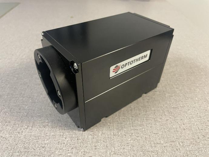
IS640 Camera (retired)
Reliable, High Speed Data Transfer
Only one cable is required to connect the IS640 camera to your computer. Radiometric image data is transferred from the camera to computer by way of a PCIe Camera Link video board. Camera Link is a high-speed serial digital bus designed specifically for machine vision cameras and offers the highest stability and throughput of any camera bus. Image data is transferred to computer memory using DMA channels that do not burden the computer’s CPU. This is essential due to the high demands placed on the CPU in processing and analyzing thermal image data. The camera is powered via 12 VDC Power over Camera Link (PoCL), eliminating the need for additional power supplies and cords. The video board includes a Universal Asynchronous Receiver Transmitter (UART) providing reliable camera control via serial communication between the IS640 and computer.
Setup
Mounting Threads
There are two ¼-20 internal threads (1.5” apart) and two M6 internal threads (25 mm apart) on the bottom of the camera that can be used for mounting the camera. When mounting the camera, make sure bolts are securely screwed into the camera’s internal threads to prevent the possibility of dropping or damaging the camera.
There are two ¼-20 internal threads (1.5” apart) and two M6 internal threads (25 mm apart) on the bottom of the camera that can be used for mounting the camera. When mounting the camera, make sure bolts are securely screwed into the camera’s internal threads to prevent the possibility of dropping or damaging the camera.
Camera Link Cable (if applicable)
-
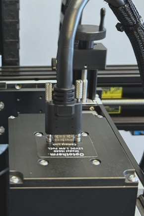
Insert the small connector end of the Camera Link cable to the mini Camera Link receptacle on the back of the camera (see Figure 1) and tighten the thumbscrews.
-
Insert the large connector end of the Camera Link cable to the Camera Link board that is installed in the computer and tighten the thumbscrews.
-
Insert the small connector end of the Camera Link cable to the mini Camera Link receptacle on the back of the camera (see Figure 1) and tighten the thumbscrews.
-
Insert the large connector end of the Camera Link cable to the Camera Link board that is installed in the computer and tighten the thumbscrews.
Cable Support
-
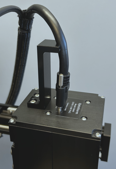
Connect the Cable Support to the back of the camera using the two (2) M4 screws provided (see Figure 2).
-
Loosen the Cable Support M3 thumbscrews and remove the Cable Clamp from the Cable Support (see Figure 2).
-
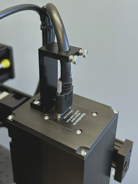
Install the Cable Clamp over the cable and tighten the thumbscrews (see Figure 3).
Figure 1: Camera link connection
Figure 2: Camera mounted cable support
Figure 3: Tighten cable clamp
-
Connect the Cable Support to the back of the camera using the two (2) M4 screws provided (see Figure 2).
-
Loosen the Cable Support M3 thumbscrews and remove the Cable Clamp from the Cable Support (see Figure 2).
-
Install the Cable Clamp over the cable and tighten the thumbscrews (see Figure 3).
Figure 1: Camera link connection
Figure 2: Camera mounted cable support
Figure 3: Tighten cable clamp
Operation
Image Capture
-
Start Thermalyze by double-clicking the Thermalyze icon on the computer desktop.
-
From the drop-down box on the top toolbar, select the lens that is currently installed on the camera.
-
From the drop-down box on the top toolbar, select the lowest temperature measurement range.
-
Press the Camera Communication Settings button  on the top toolbar within the Camera section to open the Camera Communication Settings window.
-
In the Com Port drop-down box, select the serial com port to which the camera is connected. To determine the correct com port, open Window Device Manager and expand the items under Ports (COM & LPT). There should be an entry called Matrox Solios Camera Link Com Port 0 (Com#). "#" indicates the serial com port that should be selected.
-
In the Baud Rate drop-down box, select 115,200 bps.
-
Click the Capture Image button  to begin capturing and displaying thermal images.
-
Aim the camera at an object whose temperature is higher than the ambient surroundings (such as another person) and then press the Auto Scale button to the upper right of the image in the Color Palette frame. The images may not be in focus yet, but you should be able to see movement as you pass your hand slowly in front of the camera.
Start Thermalyze by double-clicking the Thermalyze icon on the computer desktop.
From the drop-down box on the top toolbar, select the lens that is currently installed on the camera.
From the drop-down box on the top toolbar, select the lowest temperature measurement range.
Press the Camera Communication Settings button  on the top toolbar within the Camera section to open the Camera Communication Settings window.
In the Com Port drop-down box, select the serial com port to which the camera is connected. To determine the correct com port, open Window Device Manager and expand the items under Ports (COM & LPT). There should be an entry called Matrox Solios Camera Link Com Port 0 (Com#). "#" indicates the serial com port that should be selected.
In the Baud Rate drop-down box, select 115,200 bps.
Click the Capture Image button  to begin capturing and displaying thermal images.
Aim the camera at an object whose temperature is higher than the ambient surroundings (such as another person) and then press the Auto Scale button to the upper right of the image in the Color Palette frame. The images may not be in focus yet, but you should be able to see movement as you pass your hand slowly in front of the camera.
CE Declaration of Conformity
This is to certify that the Optotherm Infrasight Camera series has been designed and manufactured to meet the requirements, as applicable, of the EU-Directive: 2014/30/EU Electromagnetic Compatibility and the following harmonizing standards. The system consequently meets the requirements for the CE-mark.
EMC Specifications
The Optotherm Infrasight Camera series has been subjected to, and been shown to comply with, the EMC (Electromagnetic Compatibility) tests listed below in accordance with the requirements of the following specifications:
-
IEC 60601-1-2 (4th Edition 2014 07): Medical electrical equipment – Part 1-2: General requirements for basic safety and essential performance – Collateral Standard: Electromagnetic disturbances – Requirements and tests
-
EN 61000-6-1:2007: Electromagnetic compatibility (EMC) - Part 6-1: Generic standards - Immunity standard for residential, commercial, and light-industrial environments
-
EN 61000-6-3:2007/A1:2011: Electromagnetic compatibility (EMC) – Part 6-3: Generic standards – Emission standard for residential, commercial, and light-industrial environments
-
EN 61326-1:2013: Electrical equipment for measurement, control, and laboratory use - EMC requirements Part 1: General requirements
EMC Tests Performed
-
EN 55011:2009 - Radiated Emissions - Class B 30MHz - 1GHz
-
EN 61000-4-2:2008 - Electrostatic Discharge Immunity - 2kV, 4kV, 8kV, 15kV (Air), 8kV (contact)
-
EN 61000-4-3:2010 - Radiated Electromagnetic Field Immunity - 80MHz to 2.7GHz @ 10V/m 80% AM @ 1kHz
-
EN 61000-4-3:2010 - Proximity Fields from RF Wireless - 80MHz to 2.7GHz @ 10V/m 80% AM @ 1kHz
-
EN 61000-4-4:2012 - Fast Transient/Burst Immunity - I/O Lines (1kV)
-
EN 61000-4-6:2013 - Conducted RF Immunity - 3Vrms (150kHz - 80MHz)
-
EN 61000-4-8:2009 - Magnetic Field Immunity - 30A/m @ 50Hz & 60 Hz
EN 55011:2009 - Radiated Emissions - Class B 30MHz - 1GHz
EN 61000-4-2:2008 - Electrostatic Discharge Immunity - 2kV, 4kV, 8kV, 15kV (Air), 8kV (contact)
EN 61000-4-3:2010 - Radiated Electromagnetic Field Immunity - 80MHz to 2.7GHz @ 10V/m 80% AM @ 1kHz
EN 61000-4-3:2010 - Proximity Fields from RF Wireless - 80MHz to 2.7GHz @ 10V/m 80% AM @ 1kHz
EN 61000-4-4:2012 - Fast Transient/Burst Immunity - I/O Lines (1kV)
EN 61000-4-6:2013 - Conducted RF Immunity - 3Vrms (150kHz - 80MHz)
EN 61000-4-8:2009 - Magnetic Field Immunity - 30A/m @ 50Hz & 60 Hz


