Lens Uniformity Correction
Procedure: Lens calibration is an intricate process involving rigorous procedures and requiring accurate temperature measurements. If the instructions in this manual are not followed precisely, non-radiometric thermal images may result.
Do not touch the black painted surface of the calibration plate. Doing so will change its emissivity properties and non-radiometric thermal images may result.
Thermal Camera Position
Position the thermal camera directly above the calibration plate at the distance listed in the table below. Distance is determined by the lens installed. Distance is measured from the front of the lens housing to the top surface of the calibration plate. If calibrating the Macro lens, adjust the focus ring to closest focus by turning the ring full clockwise (from the front of the camera). This distance deliberately places the calibration plate out-of-focus to prevent imperfections on the plate from affecting uniformity correction.
| IS640 lens | Uniformity Correction Distance |
| Macro | 30mm |
| 80µm |
50mm |
| 40µm |
35mm |
| 20µm |
40mm |
| 5µm |
30mm |
Thermalyze Software: See Thermalyze Operation documentation for Lens Calibration software features and operation.
Software Setup
-
Start Thermalyze.
-
Select the Calibration Range to calibrate.
-
Start capturing thermal images.
-
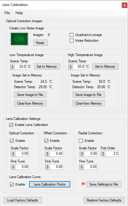
Open the Lens Calibration window (see Figure 1) by selecting the Lens Calibration item under the Setup menu.
-
In the Create Low Noise Image group box, make sure Quadrant Average and Noise Reduction are unchecked.
-
In the Lens Calibration Settings panel, uncheck Enable Lens Calibration.
Figure 1: Lens Calibration window
Create Low Temperature Image
-
Make sure the thermoelectric chuck is set to 20°C and allow the calibration plate temperature to stabilize by observing the RTD Thermometer readings.
-
Click the Reset button to remove any previously accumulated images.
-
Make sure the thermal camera and lens temperature are stable by confirming that the lens name field background is green. This field will be yellow if nearly stable and red if unstable.
-
Press the large green button to the ON state to start accumulating images. Accumulated images are averaged together to create a low noise image.
-
Press the button to the OFF state after at least 500 images have been accumulated.
-
In the Low Temperature Image panel, set Scene Temp to 20°C.
-
Click the Set to Memory button.
-
Click the Save Image to File button.
Create High Temperature Image
-
Set the thermoelectric chuck to the temperature listed in the table below. Temperature is determined by the lens installed and current calibration range. Allow the calibration plate temperature to stabilize by observing the RTD Thermometer readings.
-
Click the Reset button to remove any previously accumulated images.
-
Make sure the thermal camera and lens temperature are stable by confirming that the lens name field background is green. This field will be yellow if nearly stable and red if unstable.
-
Press the large green button to the ON state to start accumulating images. Accumulated images are averaged together to create a low noise image.
-
Press the button to the OFF state after at least 500 images have been accumulated.
-
In the High Temperature Image panel, set Scene Temp to the thermoelectric chuck temperature.
-
Click the Set to Memory button.
-
Click the Save Image to File button.
|
IS640 Lens |
High Temperature Image
|
| Macro |
Low Range: 40°C High Range: 50°C |
| 80µm |
Low Range: 40°C High Range: 50°C |
| 40µm |
Low Range: 40°C High Range: 50°C |
| 20µm |
Low Range: 40°C High Range: 50°C |
| 5µm |
Low Range: 50°C High Range: 60°C |
Lens Radiometry Correction
Calibration Plate Setup
Place the heat shield on the calibration plate and position it so that the hole in the shield is in the center of the plate. The heat shield will limit lens heating and reduce calibration inaccuracy.
Thermal Camera Position
Position the thermal camera directly above the calibration plate at the distance listed in the table below. Distance is determined by the lens installed. Distance is measured from the front of the lens housing to the top surface of the calibration plate. If calibrating the Macro lens, adjust the focus ring to focus on the calibration plate. This distance places the calibration plate in focus.
| IS640 Lens |
Radiometry Correction Distance |
| Macro |
100mm |
| 80µm |
69mm |
| 40µm |
27mm |
| 20µm |
31mm |
| 5µm |
19.5mm |
Thermalyze Software: See Thermalyze Operation documentation for Lens Calibration Points software features and operation.
General Software Setup
-
Start Thermalyze.
-
Enable Image Averaging and set to 32 images.
-
Create a rectangle region in the center of the thermal image approximately 50 x 50 pixels.
-
Select the Calibration Range to calibrate.
-
Start capturing thermal images.
Lens Calibration Points Window Setup
-
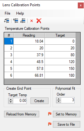
Open the Lens Calibration Points window (see Figure 1) by clicking the Lens Calibration Points button on the Lens Calibration window.
-
In the Polynomial Fit panel, set Order to 3.
-
Click the Delete All Cal Points button
to remove all obsolete calibration points.
Figure 1: Lens Calibration Points window
Enter Reading and Target Temperatures
-
Set the thermoelectric chuck to the first target temperature listed in the table below. Temperature is determined by the lens installed and current calibration range. Allow the calibration plate temperature to stabilize by observing the RTD Thermometer readings.
-
Make sure the thermal camera and lens temperature are stable by confirming that the lens name field background is green. This field will be yellow if nearly stable and red if unstable.
-
Click the Add New Cal Point button to add a new row to the Temperature Calibration Points table. Note: To move the new row to the desired position, click and select the row to move and then click the Shift Cal Point Up and Shift Cal Point Down buttons.
-
Enter the mean temperature value of the rectangle region (displayed in the Region Data Grid) into the Reading field.
-
Enter the RTD Thermometer reading into the Target field.
-
Return to step 1 using the next target temperature. Proceed to the next step after the last target temperature has been processed.
|
IS640 Lens |
Target Temperatures
|
| Macro |
Low Range: 10, 30, 50, 70°C High Range: 20, 40, 60, 80°C* |
| 80µm |
Low Range: 10, 30, 50, 70°C High Range: 20, 40, 60, 80°C* |
| 40µm |
Low Range: 10, 20, 30, 40°C High Range: 20, 40, 60, 80°C* |
| 20µm |
Low Range: 10, 30, 50, 70°C High Range: 20, 40, 60, 80°C* |
| 5µm |
Low Range: 20, 40, 60, 80°C High Range: 20, 40, 60, 80°C* |
* Higher target temperatures may be used depending on the temperature range of the thermoelectric chuck model. Note however, that high thermal stage temperatures may increase lens temperature, reducing calibration accuracy.
Create End Points
-
End points are calibration points added to the beginning and end of the range of Target values and help prevent divergence of the polynomial curve fit at the curve extremes.
-
Enter a value in the Target Temp field that is 10°C below the lowest target temperature in the table.
-
Click the Create button to create and add the low end point to the table.
-
Enter a value in the Target Temp field that is 10°C above the highest target temperature in the table.
-
Click the Create button to create and add the high end point to the table.
Save Data
-
Click the Set to Memory button.
-
Click the Save Image to File button.
Enable Lens Calibration
Procedure
-
Open the Lens Calibration window (see Figure 1).
-
In the Lens Calibration Settings panel, check Enable Lens Calibration.
-
In the Optical Correction panel, check Enable.
-
In the Offset Correction panel, check Enable.
-
In the Radial Correction panel, uncheck Enable.
-
In the Optical Correction and Offset Correction panels, enter the appropriate values for the Scale Factor and Fine-Tune listed in the table below. Values are determined by the lens installed and current calibration range.
-
In the Lens Calibration Curve panel, check Enable.
-
Click the Save Settings to File button.
Figure 1: Lens Calibration window
|
IS640 Lens |
Optical Correction Scale Factor
|
Offset Correction Scale Factor
|
| Macro |
Low Range: 0.75 High Range: 0.6 |
Low Range: 0 High Range: 0 |
| 80µm |
Low Range: 0.67 High Range: 0.52 |
Low Range: 0 High Range: 0 |
| 40µm |
Low Range: 0.5 High Range: 0.5 |
Low Range: -0.65 High Range: -0.52 |
| 20µm |
Low Range: 0.0 High Range: 0.0 |
Low Range: 0 High Range: 0 |
| 5µm |
Low Range: 0.85 High Range: 0.85 |
Low Range: 0.7 High Range: 0.7 |


