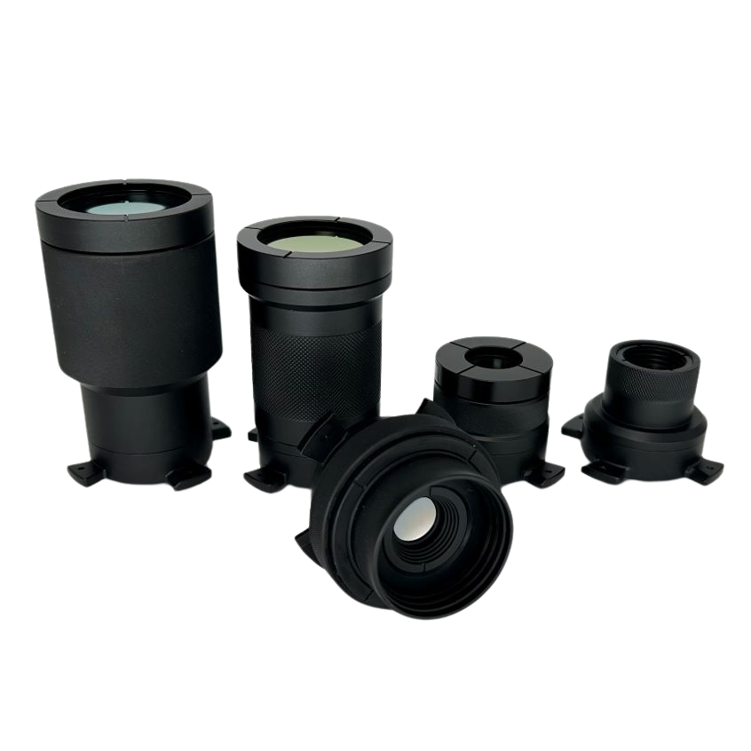
Infrasight Lenses
We developed a full suite of infrared lenses, enabling both microscopic and macroscopic temperature measurement. Lenses are manufactured from Germanium, Zinc Selenide, and Zinc Sulfide with anti-reflective coatings for maximum transmission in the long wave infrared region. Each lens is designed for maximum sensitivity, long working distance, and with minimum distortion for clear, precise imaging. We developed a bayonet-style mechanical interface enabling quick lens attachment and removal while maximizing thermal uniformity between the lens and camera body to maintain the high measurement accuracy.
Applications
- Semiconductor device failure analysis
- Circuit board failure analysis
- Microscopic temperature measurement and analysis of materials
Overview
Comprehensive Calibration
Each lens is calibrated while installed on the camera, resulting in unsurpassed accuracy and measurement uniformity across the entire field-of-view.
Included Components
- Shock resistant carrying case
Required Products
Related Products

IS640 Macro Lens
PN0120
This lens has an adjustable focus and working distance range of 100 mm out to infinity. The maximum spatial resolution is 140µm/pixel.
Application: Imaging large devices and circuit board assemblies.

IS640 80 Micron Lens
PN0119
Optimized with high numerical aperture for optimal measurement sensitivity and spatial resolution, this fixed-focus lens provides 80µm/pixel spatial resolution and 51.2 x 38.4 mm field-of-view at a working distance of 69 mm.
Application: Imaging larger electronic devices such as ball grid arrays.

IS640 40 Micron Lens
PN0117
Optimized with the highest numerical aperture (NA) of all Sentris lenses, this fixed-focus lens provides 40µm/pixel spatial resolution and 25.6 x 19.2 mm field-of-view at a working distance of 27 mm (see Figure 1).
To achieve this high NA, the performance in the center 12.8 x 9.6 mm FOV is optimized, resulting in slightly reduced performance outside of center. For this reason, this lens is not radiometric and high measurement accuracy cannot be assured.
Application: We designed this lens specifically for lock-in thermography (LIT) to minimize test time and to detect extremely low localized heating. With twice the sensitivity of the 20µm and 80µm lenses, LIT test time can be reduced by a factor of four.

IS640 20 Micron Lens
PN0116
Optimized with high numerical aperture for optimal measurement sensitivity and spatial resolution, this fixed-focus lens provides 20µm/pixel spatial resolution and 12.8 x 9.6 mm field-of-view at a working distance of 31 mm.
Application: Imaging small electronic devices and packages.

IS640 10 Micron Lens
PN0653
Optimized for high spatial resolution, this fixed-focus lens provides 10µm/pixel spatial resolution and 6.4 x 4.8 mm field-of-view at a working distance of 20 mm.
Application: Imaging small electronic devices and packages.

IS640 5 Micron Lens
PN0118
Optimized for high spatial resolution, this fixed-focus lens provides 5µm/pixel spatial resolution and 3.2 x 2.4 mm field-of-view at a working distance of 19.5 mm. Although we calibrate this lens, due to its large size and low numerical aperture, lens thermal gradients can result in measurement accuracy drift of more than 10°C. For this reason, this lens is not radiometric and high measurement accuracy cannot be assured.
Application: It is used primarily for semiconductor failure analysis in lock-in thermography tests where absolute accuracy is not required, but relative measurements between pixels is important.
Specifications
Optics
| Lens |
IS640 Macro Lens PN0120 |
IS640 80 Micron Lens PN0119 |
IS640 40 Micron Lens PN0117 |
IS640 20 Micron Lens PN0116 |
IS640 10 Micron Lens PN0653 |
IS640 5 Micron Lens PN0118 |
|
Pixel Resolution
|
Minimum 140 μm resolution (at 100 mm) |
80 µm |
40 µm |
20 µm |
10 µm |
5 µm |
|
Focus
|
Manual |
Fixed |
Fixed |
Fixed |
Fixed |
Fixed |
|
Working Distance
|
100 mm to infinity |
69 mm |
27 mm |
31 mm |
20 mm |
19.5 mm |
|
Field of View
|
89.6 x 67.2 mm minimum |
51.2 x 38.4 mm |
25.6 x 19.2 mm |
12.8 x 9.6 mm |
6.4 x 4.8 mm |
3.2 x 2.4 mm |
|
Focal Length
|
12 mm |
16.3 mm |
15.2 mm |
36.4 mm |
40.9 mm |
20.6 mm |
|
Working F/#
|
1.00 |
1.05 |
0.76 |
1.09 |
1.41 |
2.62 |
| Object Space NA | 0.003 | 0.10 | 0.28 | 0.39 | 0.60 | 0.65 |
| Depth of Field | Dependent on working distance | ±900µm | ±120µm |
±40µm |
±25µm |
±15µm |
Measurement
|
Calibration Range †
|
Low range: 10 to 80°C * High range: 10 to 300°C |
Low range: 10 to 80°C * High range: 10 to 300°C |
Low range: 10 to 60°C * High range: 10 to 250°C |
Low range: 10 to 80°C * High range: 10 to 300°C |
Low range: 10 to 80°C * High range: 10 to 300°C |
10 to 300°C * |
|
Sensitivity (NETD) ‡
|
Low range: < 35 mK (60 Hz) High range: < 70 mK (60 Hz) |
Low range: < 35 mK (60 Hz) High range: < 70 mK (60 Hz) |
Low range: < 25 mK (60 Hz) High range: < 50 mK (60 Hz) |
Low range: < 35 mK (60 Hz) High range: < 70 mK (60 Hz) |
Low range: < 50 mK (60 Hz) High range: < 90 mK (60 Hz) |
< 300 mK |
|
Accuracy
|
Low range: +/-2°C High range: +/-2°C or 2% of reading § |
Low range: +/-2°C High range: +/-2°C or 2% of reading § |
Non-radiometric (used for lock-in thermography testing) |
Low range: ± 2°C High range: ± 2°C or 2% of reading § |
Low range: ± 2°C High range: ± 2°C or 2% of reading § |
Non-radiometric (designed for lock-in thermography testing and spatial/temporal relative measurements) |
* Sentris low range calibrations are optimized for highest sensitivity and may have reduced calibration range.
† The calibration range stated in the specification indicates the range of black-body temperatures used during calibration. Temperature measurements outside of the stated range may be able to be performed but may not meet the specified measurement accuracy.
‡ Noise Equivalent Temperature Difference (NETD) specifies the smallest temperature difference that can be detected. The value stated is NETD at 60 Hz frame rate. Activating real-time image averaging can improve NETD but will increase the measurement response time.
§ whichever is greater
Optical Magnification Comparison
Optical magnification is calculated by dividing the sensor pixel size (17µm) by the lens image pixel size.
|
Image pixel size |
Optical Magnification
|
| 80µm |
17/80 = 0.2125x |
| 40µm |
17/40 = 0.425x |
| 20µm |
17/20 = 0.85x |
| 10µm |
17/10 = 1.7x |
| 5µm |
17/5 = 3.4x |
Width of a line in micrometers in USAF Resolving Power Test Target 1951
|
|
Group Number | -2 | -1 | 0 | 1 | 2 | 3 | 4 | 5 | 6 | 7 | 8 | 9 |
|
Element
|
|
|
|
|
|
|
|
|
|
|
|
|
|
| 1 | 2000.00 | 1000.00 |
500.00 |
250.00 |
125.00 |
62.50 |
31.25 |
15.63 |
7.81 |
3.91 |
1.95 |
0.98 |
|
| 2 |
|
1781.80 |
890.90 |
445.45 |
222.72 |
111.36 |
55.68 |
27.84 |
13.92 |
6.96 |
3.48 |
1.74 |
0.87 |
| 3 |
|
1587.40 |
793.70 |
396.85 |
198.43 |
99.21 |
49.61 |
24.80 |
12.40 |
6.20 |
3.10 |
1.55 |
0.78 |
| 4 |
|
1414.21 |
707.11 |
353.55 |
176.78 |
88.39 |
44.19 |
22.10 |
11.05 |
5.52 |
2.76 |
1.38 |
0.69 |
| 5 |
|
1259.92 |
629.96 |
314.98 |
157.49 |
78.75 |
39.37 |
19.69 |
9.84 |
4.92 |
2.46 |
1.23 |
0.62 |
| 6 |
|
1122.46 |
561.23 |
280.62 |
140.31 |
70.15 |
35.08 |
17.54 |
8.77 |
4.38 |
2.19 |
1.10 |
0.55 |
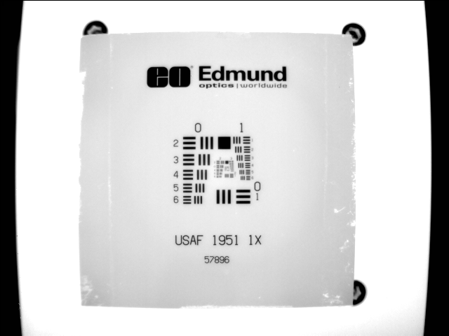
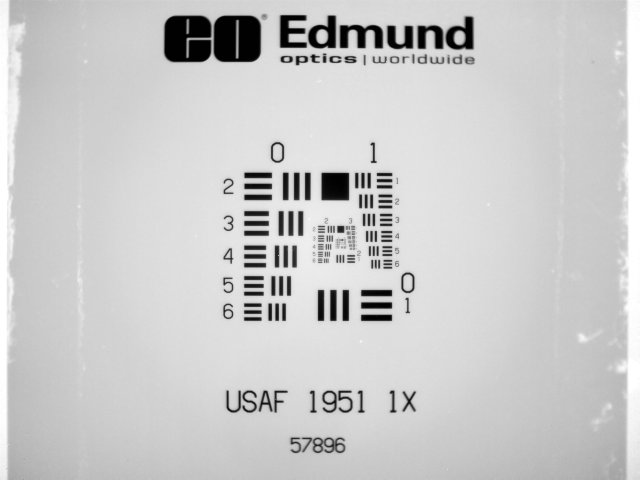
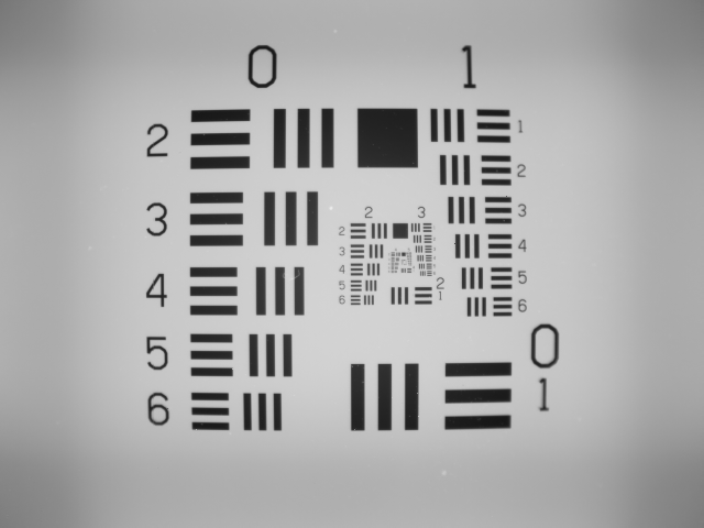
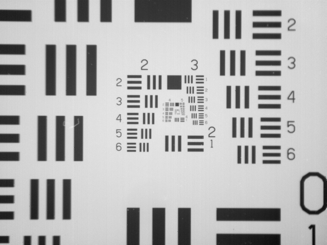

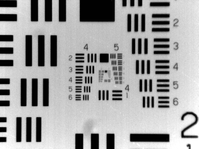
Figure 1: From left to right: USAF 1951 chart from Macro, 80µm, 40µm, 20µm, 10µm, 5µm lens perspective
Setup
Delicate Lenses: Infrared lenses have glass-like properties and can be scratched, chipped, or shattered if mishandled. Additionally, there is a delicate coating on the surface of the lens to maximize transparency of long wavelength energy. Therefore, avoid touching the lens elements with your hands or with any hard or rough materials and handle them using the knurled installation grip.
Installing a Lens
While installing the lens, use both hands to prevent accidentally dropping the lens.
- Remove the new lens from the lens case.
- Remove the front and back lens protection caps and place them back in the lens case.
-
The lens flanges seat flat against the front of the camera.
Lens Install: The lens flanges seat flat against the front of the camera. Make sure there is no dirt or grit on the flanges prior to installing a lens.
- Grasp the knurled grip and orient the wide lens flange over the wide receptacle that is located near the top of the camera. Insert the four flanges of the lens into the camera. While gently pressing the lens against the camera, twist the lens clockwise (looking at the front of the camera) to install the lens. You will hear a soft click when the lens is securely seated and the internal ball springs push the lens flanges tight against the camera.
Lens Temperature: When a new lens is installed, you may need to wait a few minutes until an equilibrium temperature is reached between the new lens and camera to conduct accurate temperature measurements.
Removing a Lens
- Make sure the camera is aimed horizontally or downward to prevent dust or debris from entering the lens housing and damaging the camera detector.
-
Start Thermalyze and press the Capture Images button
 to open the camera shutter.
- Using both hands to prevent accidental dropping the lens (see Figure 2), grasp the knurled lens grip and gently twist the lens counterclockwise until the ball springs are disengaged and then slowly withdraw the lens from the camera. Place the lens protection caps on both ends of the lens and place the lens into the lens case for protection. Caution: Do not touch the lens glass during this procedure.

Figure 2: Removing a Lens
Operation
Lens Focusing
The macroscopic lens has a focus ring that is rotated to bring the image into focus. All microscopic lenses have fixed focus and therefore the entire camera must be moved toward/away from an object using the Vertical Stage to focus the image.
Lens Contact: Microscopic lenses have short working distances. Therefore, to avoid damaging the lens, use caution when lowering the camera using the Vertical Stage to prevent contacting the lens with the unit under test or system component.
Maintenance
Lens Cleaning
Delicate Lenses: Please follow these instructions carefully to avoid lens damage.
Precautions
To protect the lens from damage, follow these guidelines.
- Never touch the lens with hard or abrasive objects.
- Do not use solvents to clean the lens. Solvents may remove the lens coating.
- Do not use lens cleaning papers or tissues to wipe the lens. These products are abrasive and will scratch the lens.
Lens Cleaning Kit
This is provided with your camera and includes the following components.
- Air bulb blower
- Lens cleaning solution
- Wiping cloth
- Cotton swabs
Lens cleaning Procedure
Excessive dust or debris on the camera lens can reduce measurement accuracy. To clean the lens, follow this procedure.
- Use the air bulb blower and brush to remove any dust or loose grit from the lens.
- Put a few drops of the cleaning solution on the cloth and gently wipe across the lens (not round and round). Use only enough pressure to remove the smudges (do not rub hard).
- Use the cotton swabs for tougher lens grime but avoid rubbing the same spot over and over.