
Overview
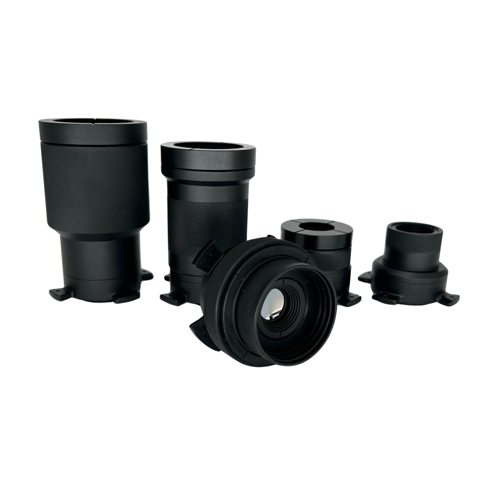
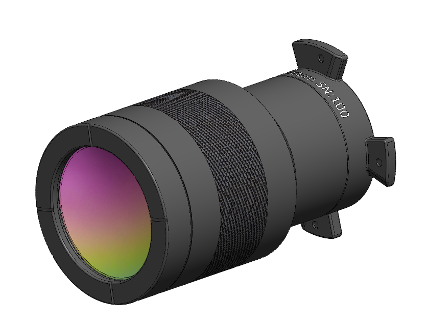
We developed a full suite of infrared lenses, enabling both microscopic and macroscopic temperature measurement. Lenses are manufactured from Germanium, Zinc Selenide, and Zinc Sulfide with anti-reflective coatings for maximum transmission in the long wave infrared region. Each lens is designed for maximum sensitivity, long working distance, and with minimum distortion for clear, precise imaging. We developed a bayonet-style mechanical interface enabling quick lens attachment and removal while maximizing thermal uniformity between the lens and camera body to maintain the high measurement accuracy.
Applications
- Semiconductor device failure analysis
- Circuit board failure analysis
- Microscopic temperature measurement and analysis of materials
Features
Comprehensive Calibration
Each lens is calibrated while installed on the camera, resulting in unsurpassed accuracy and measurement uniformity across the entire field-of-view.
Specifications
Optics
Pixel Resolution | Focus | Working Distance | Field of View | Focal Length | Working F/# | Object Space NA | Depth of Field | |
[PN0118] IS640-17 LWIR Lenses (5 micron) | 5 µm | Fixed | 19.5 mm | 3.2 x 2.4 mm | 20.6 mm | 2.62 | 0.65 | ±15µm |
[PN1112] IS640-17 LWIR Lenses (C 5 Micron) | 5 µm | Fixed | 19 mm | 3.2 x 2.4 mm | 15.7 mm | 2.84 | 0.60 | ±15µm |
[PN0653] IS640-17 LWIR Lenses (10 micron) | 10 µm | Fixed | 20 mm | 6.4 x 4.8 mm | 40.9 mm | 1.41 | 0.60 | ±25µm |
[PN0116] IS640-17 LWIR Lenses (20 micron) | 20 µm | Fixed | 31 mm | 12.8 x 9.6 mm | 36.4 mm | 1.09 | 0.39 | ±40µm |
[PN0910] IS640-17 LWIR Lenses (20 micron LWD) | 20 µm | Fixed | 44 mm | 12.8 x 9.6 mm | 36 mm | 1.18 | 0.36 | ±40µm |
[PN1108] IS640-17 LWIR Lenses (C 20 micron) | 20 µm | Fixed | 35.3 mm | 12.8 x 9.6 mm | 32.7 mm | 1.15 | 0.35 | ±40µm |
[PN0117] IS640-17 LWIR Lenses (40 micron) | 40 µm | Fixed | 27 mm | 25.6 x 19.2 mm | 15.2 mm | 0.76 | 0.28 | ±120µm |
[PN0911] IS640-17 LWIR Lenses (40 micron LWD) | 40 µm | Fixed | 86 mm | 25.6 x 19.2 mm | 35 mm | 1.02 | 0.21 | ±120µm |
[PN0119] IS640-17 LWIR Lenses (80 micron) | 80 µm | Fixed | 69 mm | 51.2 x 38.4 mm | 16.3 mm | 1.05 | 0.10 | ±900µm |
[PN1113] IS640-17 LWIR Lenses (C 80 Micron) | 80 µm | Fixed | 116 mm | 51.2 x 38.4 mm | 14.4 mm | 1.11 | 0.10 | ±900µm |
[PN0120] IS640-17 LWIR Lenses (Variable Focus Macro) | 140 μm min resolution (at 100 mm WD) | Manual | 100 mm to infinity | 89.6 x 67.2 mm minimum | 12 mm | 1.00 | 0.003 | Dependent on working distance |
[PN1111] IS640-17 LWIR Lenses (WFOV Variable Focus) | 40 μm (15 mm WD*) 961 µm (778 mm WD) | Manual | 15 to 778 mm | 25.6 x 19.2 mm 615 x 461 mm | 15.1 mm | 1.13 | 0.202 | ±300µm |
* Working distance
Measurement
Calibration range † | Sensitivity (NETD) ‡ | Accuracy | |
[PN0118] IS640-17 LWIR Lenses (5 micron) | 10 to 300°C * | < 300 mK | Non-radiometric (designed for lock-in thermography testing and spatial/temporal relative measurements) |
[PN1112] IS640-17 LWIR Lenses (C 5 Micron) | 10 to 300°C * | < 300 mK | Non-radiometric (designed for lock-in thermography testing and spatial/temporal relative measurements) |
[PN0653] IS640-17 LWIR Lenses (10 micron) | Low range: 10 to 80°C * High range: 10 to 300°C | Low range: < 50 mK (60 Hz) High range: < 90 mK (60 Hz) | Low range: ± 2°C High range: ± 2°C or 2% of reading § |
[PN0116] IS640-17 LWIR Lenses (20 micron) | Low range: 10 to 80°C * High range: 10 to 300°C | Low range: < 35 mK (60 Hz) High range: < 70 mK (60 Hz) | Low range: ± 2°C High range: ± 2°C or 2% of reading § |
[PN0910] IS640-17 LWIR Lenses (20 micron LWD) | Low range: 10 to 80°C * High range: 10 to 300°C | Low range: < 35 mK (60 Hz) High range: < 70 mK (60 Hz) | Low range: ± 2°C High range: ± 2°C or 2% of reading § |
[PN1108] IS640-17 LWIR Lenses (C 20 micron) | Low range: 10 to 80°C * High range: 10 to 300°C | Low range: < 35 mK (60 Hz) High range: < 70 mK (60 Hz) | Low range: ± 2°C High range: ± 2°C or 2% of reading § |
[PN0117] IS640-17 LWIR Lenses (40 micron) | Low range: 10 to 60°C * High range: 10 to 250°C | Low range: < 25 mK (60 Hz) High range: < 50 mK (60 Hz) | Non-radiometric (designed for lock-in thermography testing and spatial/temporal relative measurements) |
[PN0911] IS640-17 LWIR Lenses (40 micron LWD) | Low range: 10 to 80°C * High range: 10 to 300°C | Low range: < 35 mK (60 Hz) High range: < 70 mK (60 Hz) | Low range: ± 2°C High range: ± 2°C or 2% of reading § |
[PN0119] IS640-17 LWIR Lenses (80 micron) | Low range: 10 to 80°C * High range: 10 to 300°C | Low range: < 35 mK (60 Hz) High range: < 70 mK (60 Hz) | Low range: +/-2°C High range: +/-2°C or 2% of reading § |
[PN1113] IS640-17 LWIR Lenses (C 80 Micron) | Low range: 10 to 80°C * High range: 10 to 300°C | Low range: < 35 mK (60 Hz) High range: < 70 mK (60 Hz) | Low range: +/-2°C High range: +/-2°C or 2% of reading § |
[PN0120] IS640-17 LWIR Lenses (Variable Focus Macro) | Low range: 10 to 80°C * High range: 10 to 300°C | Low range: < 35 mK (60 Hz) High range: < 70 mK (60 Hz) | Low range: +/-2°C High range: +/-2°C or 2% of reading § |
[PN1111] IS640-17 LWIR Lenses (WFOV Variable Focus) | Low range: 10 to 80°C * High range: 10 to 300°C | Low range: < 35 mK (60 Hz) High range: < 70 mK (60 Hz) | Low range: +/-2°C High range: +/-2°C or 2% of reading § |
* Sentris low range calibrations are optimized for highest sensitivity and may have reduced calibration range.
† The calibration range stated in the specification indicates the range of black-body temperatures used during calibration. Temperature measurements outside of the stated range may be able to be performed but may not meet the specified measurement accuracy.
‡ Noise Equivalent Temperature Difference (NETD) specifies the smallest temperature difference that can be detected. The value stated is NETD at 60 Hz frame rate. Activating real-time image averaging can improve NETD but will increase the measurement response time.
§ whichever is greater
Optical Magnification Comparison
Optical magnification is calculated by dividing the sensor pixel size (17µm) by the lens image pixel size.
| Image pixel size | Optical Magnification |
| 80µm | 17/80 = 0.2125x |
| 40µm | 17/40 = 0.425x |
| 20µm | 17/20 = 0.85x |
| 10µm | 17/10 = 1.7x |
| 5µm | 17/5 = 3.4x |
Width of a line in micrometers in USAF Resolving Power Test Target 1951
| Group Number | -2 | -1 | 0 | 1 | 2 | 3 | 4 | 5 | 6 | 7 | 8 | 9 | |
| Element | |||||||||||||
| 1 | 2000.00 | 1000.00 | 500.00 | 250.00 | 125.00 | 62.50 | 31.25 | 15.63 | 7.81 | 3.91 | 1.95 | 0.98 | |
| 2 | 1781.80 | 890.90 | 445.45 | 222.72 | 111.36 | 55.68 | 27.84 | 13.92 | 6.96 | 3.48 | 1.74 | 0.87 | |
| 3 | 1587.40 | 793.70 | 396.85 | 198.43 | 99.21 | 49.61 | 24.80 | 12.40 | 6.20 | 3.10 | 1.55 | 0.78 | |
| 4 | 1414.21 | 707.11 | 353.55 | 176.78 | 88.39 | 44.19 | 22.10 | 11.05 | 5.52 | 2.76 | 1.38 | 0.69 | |
| 5 | 1259.92 | 629.96 | 314.98 | 157.49 | 78.75 | 39.37 | 19.69 | 9.84 | 4.92 | 2.46 | 1.23 | 0.62 | |
| 6 | 1122.46 | 561.23 | 280.62 | 140.31 | 70.15 | 35.08 | 17.54 | 8.77 | 4.38 | 2.19 | 1.10 | 0.55 |
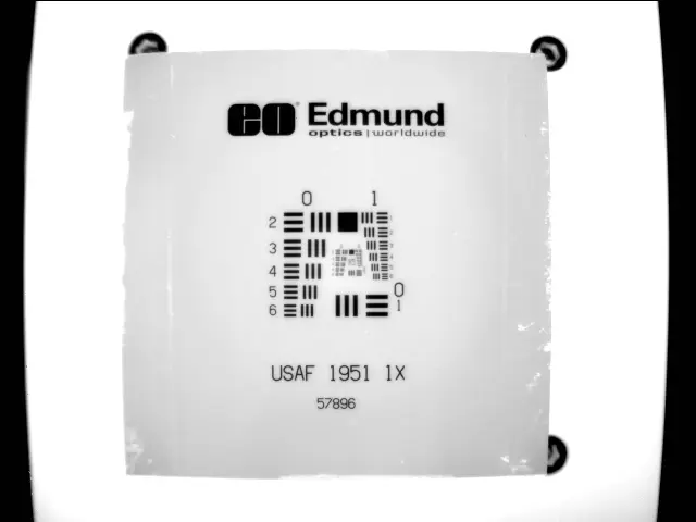
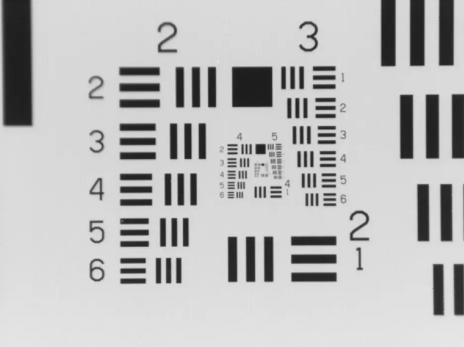

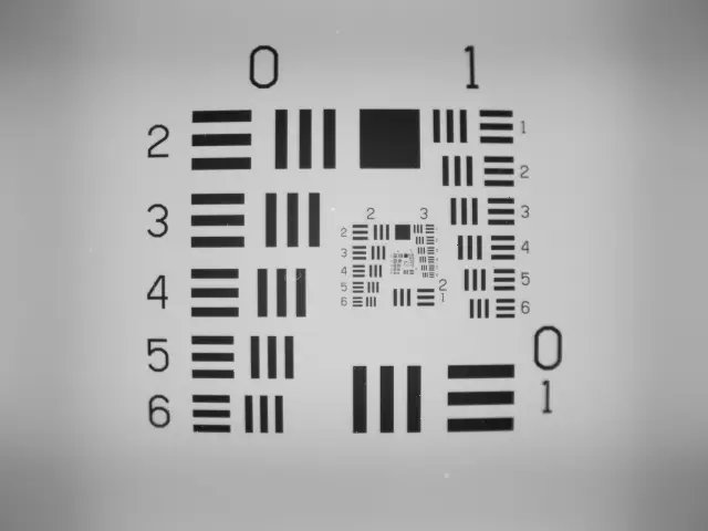

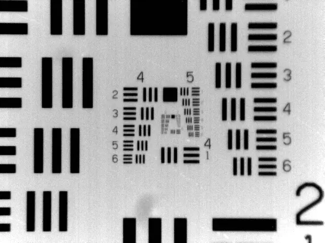
Figure 1: From left to right: USAF 1951 chart from Macro, 80µm, 40µm, 20µm, 10µm, 5µm lens perspective