8 Module Input Output Device
This product is no longer available for sale.
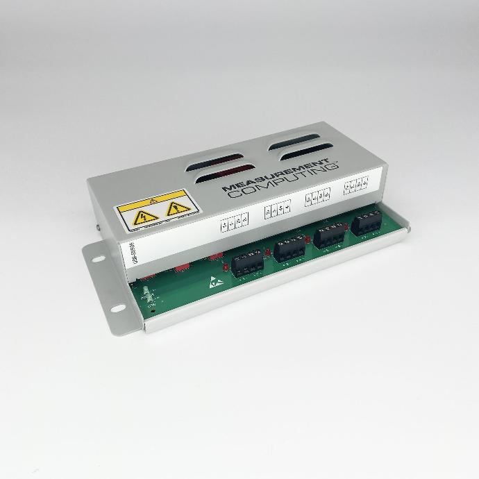
PN0616 is an I/O device with 8 channels to control and monitor relays.
Applications
-
- Controls power to devices for Lock-in Thermography, Thermal Model Comparison, and Image Sequencing tests
Overview
Included Components
Required Products
Related Products
Manufacturer Information
Specifications
| USB +5 V input voltage range |
4.75 V min to 5.25 V max |
| USB +5 V supply current (all modes of operation) |
<100 mA |
| External power input |
+6.0 VDC to 12.5 VDC ( 9 V @ 1.67 A power supply included) |
| Voltage supervisor limits - PWR LED |
6.0 V > Vext or Vext > 12.5 V: PWR LED = Off (power fault) 6.0 V ≤ Vext < 12.5 V: PWR LED = On |
| External power consumption |
All modules on, 100 mA downstream hub power: 300 mA typ, 360 mA max All modules off, 0 mA downstream hub power: 180 mA typ, 220 mA max |
| USB Type-B connector |
Input |
| USB device type |
USB 2.0 (full-speed) |
| Device compatibility |
USB 1.1, USB 2.0 |
| USB Type-A connector |
Downstream hub output port |
| USB hub type |
Supports USB 2.0 high-speed, full-speed and low-speed operating points; self-powered, 100 mA max downstream VBUS capability |
| USB cable type (upstream and downstream) |
A-B cable, UL type AWM 2527 or equivalent (min 24 AWG VBUS/GND, min 28 AWG D+/D-) |
| USB cable length |
3 meters max |
| Dimensions (L × W × H) | PCB (without modules): 203.2 × 121.9 × 22.5 mm (8.0 × 4.8 × 0.885 in.) Enclosure: 241.3 × 125.7 × 58.9 mm (9.50 × 4.95 × 2.32 in.) |
| Main connector type |
Screw terminal |
| Wire gauge range |
12 to 22 AWG |
Setup
Installation
Follow the procedure below to install the 8 Module Input Output Device. This will require installing software, hardware, and device drivers and to configure the relays.
Preinstall: If you purchased the computer from Optotherm, all of the hardware, software, and drivers have been preinstalled on the computer. The information in this section is required only when updating software or if hardware drivers or software applications needs to be reinstalled.
Software Installation
-
- Close any applications that may be running.
-
- Download MccDaq Setup and unzip using the 7-Zip File Archiver utility.
-
- Open the folder named MccDaq Setup ver… and double-click mccdaq.exe.
-
- When the “WinZip Self-Extractor - mccdaq.exe” window opens, click [Setup].
-
- On the “MCC DAQ” window, uncheck DAQami (make sure InstaCal & Universal Library is checked) and click [Install].
-
- When the “InstaCal and Universal Library” window opens, click [Next].
-
- On the “Destination Folder” screen, click [Next].
-
- On the “InstaCal and Universal Library” screen, uncheck all Universal Library Examples, and then click [Next].
-
- On the “Ready to Install the Program” screen, click [Install].
-
- If the “Window Security” window opens, check “Always trust software from Measurement Computing Corporation”, and then click [Install].
-
- On the “InstallShield Wizard Completed” screen, click [Finish].
-
- If the “DASYLAB Software” window opens, click [No Thanks].
-
- When prompted to restart the system, click [Yes].
Device Driver Installation
-
- Connect the power supply to the relay box and to a power outlet.
-
- While the computer is running, plug the relay box USB cable into an available USB port on the computer.
-
- A “USB Input Device” popup balloon may open and then close automatically.
Relay Configuration
-
- Click [Start] on the Windows taskbar, then search and select InstaCal to open the “InstaCal” window.
-
- If the “System Modifications Required” window opens, click [Yes] and continue with step 3. If this window does not open, proceed to step 6.
-
- When the “HID Registry Updater” window opens, click [Update].
-
- When prompted, cycle power to the relay box and then close the window.
-
- Repeat step 1 to run InstaCal.
-
- When the “Plug and Play Board Detection” window opens, click [OK].
-
- Close the “InstaCal” window.
Operation
I/O Module Configuration
Modules 1-4
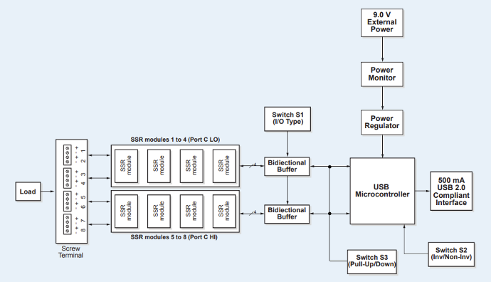
Selectable with switch S1 in the CL position as either input or output (default) modules. Switch settings for direction can be read back with software. Do not mix input and output modules within this bank of four.
Modules 5-8
User-selectable with switch S1 in the CH position as either input modules or output (default) modules. Switch settings for direction can be read back with software. Do not mix input and output modules within this bank of four.
I/O module logic polarity
Selectable with switch S2. Switch settings for polarity can be read back with software. Default to non-inverted. For input modules, invert mode returns a 1 when module is active; non-invert mode returns a 0 when module is active. For output modules, invert mode allows users to write a 1 to activate the module; non-invert mode allows users to write a 0 to activate the module.
Pull-up/pull-down on digital I/O lines
Configurable with switch S3 with 2.2 kΩ resistor network. Switch settings for pull-up/pull-down selection can be read back with software. Default to pull-up. Switch settings are applicable during power up conditions of output modules only. Modules are active Low. When switch to Pull-up, modules are inactive on power up. When switched to pulldown, modules are active on power up.
Figure 1: USB-SS408 Block Diagram
Troubleshoot
Maintenance
