Thermoelectric Vacuum Chuck
PN0255
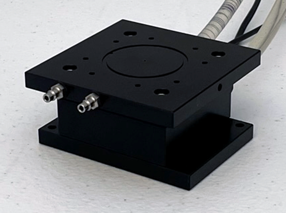
The TE Vacuum Chuck provides an 80mm x 80mm platform on which small electronic devices are heated or cooled. The stage is comprised of a top hot/cold plate and bottom heat sink. The platform has center and outer ring vacuum ports for holding down devices of different sizes.
Applications
- Securing devices for controlled temperature testing
Overview
Included Components
- Liquid coolant fittings and tubing
- Chuck device hold, set of 4
- 80 x 80mm polyimide insulation squares
-
Mounting hardware and tools
Included In
Required Products
Related Products
Manufacturer Information
Specifications
Stage Platform
Platform Size |
80 x 80mm |
Chuck Height | 42.8mm |
Chuck Weight (with coolant tubing) | 1.05kg |
Center Vacuum Port Dimensions | 1mm OD |
Outer Vacuum Ring Port Dimensions | 36mm ID, 40mm OD (2mm thick ring) 0.5mm deep |
Surface Mounting Holes (x8) |
M3 |
Temperature Range |
0-150°C |
Thermoelectric Module
| Max Current | 11.3 A |
| Max Voltage | 24.6 VDC |
| Operation Temperature | -40 °C to +200 °C |
Setup
Installation
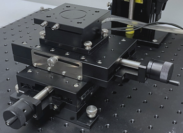
Mount Vacuum Chuck on [PN0253] Device Positioning Stage Manual XY 100 x 160mm
- Carefully place the vacuum chuck on the XY stage so that the cables and tubes exit to the rear and the vacuum ports exit to the front.
- Align the holes on the bottom of the chuck with the holes on top of the stage and secure with the four (4) M4 thumbscrews provided (see Figure 1).
Figure 1: Mounting the vacuum chuck
Mount Devices
Devices can be mounted on the top plate using the M3 internal threads. To efficiently heat/cool a sample, it is important to have good thermal transfer between the device and stage top plate. If the bottom of the device is uneven, thermal padding is available in a wide range of thicknesses and can be placed between the device and top plat to improve heat transfer.
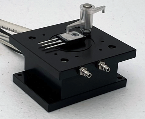
Device Spring Clamp
This spring-loaded clamp (see Figure 2) screws into the top plate of the stage and is used to secure devices and small boards. Clamps have fingers at two different heights that can accommodate device thickness up to 18 mm. The clamp is comprised of anodized aluminum with stainless thumbscrew and can withstand temperatures up to 150°C.
Figure 2: Device Spring Clamp
Lens Heating
Camera Temperature
The internal temperature of the thermal camera is displayed in real-time in the status bar at the bottom of the Thermalyze window. When operating the Thermoelectric Vacuum Stage at temperatures above 40°C for long periods with a microscopic lens installed and focused on a device, the thermal camera temperature will slowly increase. The camera is calibrated to maintain accuracy within a defined ambient temperature range (see specifications in the Sentris IS640 Thermal Imaging Camera User Manual). As the camera temperature increases above this range, measurement accuracy gradually decreases. To prevent camera heating, raise the camera at least 20 mm above its focus height while measurements are not being conducted.
Insulation Sheets
Another effective method to prevent camera temperature increase is to expose only the areas of the device that need to be imaged. Cover exposed areas of the Thermoelectric Vacuum Stage and areas of the device not being imaged using the 3 mm thick polyimide insulation sheets included. Polyimide insulation can withstand temperatures up to 285°. Cut the sheets as necessary to accommodate the profiles of your device using a utility knife.
Troubleshoot
Maintenance

