Liquid Coolant Heat Exchanger with Hardware
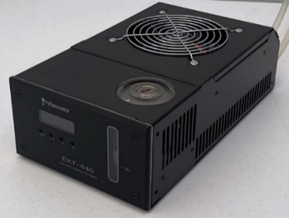
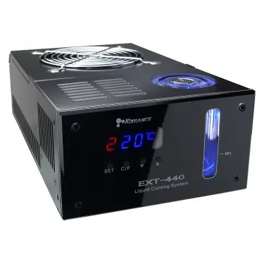
PN0317 pumps non-conductive fluid through the heat sink, drawing away heat transferred from the top plate when in cooling mode. The exchanger is placed away from the thermal camera and stage to prevent air current from the exchanger fan from interfering with sensitive failure analysis tests.
Applications
- Heating/cooling using [PN0255] Thermoelectric Vacuum Chuck
Overview
Included Components
- [PN0232] Liquid Coolant Fitting
- [PN0234] Liquid Coolant
- [PN0265] Heat Exchanger Power Adapter
Included In
Required Products
Related Products
Manufacturer Information
Specifications
Manufacturer Specifications Sheet
| Dimensions | 315 x 162 x 93mm |
| Dry Weight | 2.6kg |
|
Cooling Capacity |
400 W |
Setup
Connect Power Supply
- Insert power cord into the barrel jack located on the power adapter on the back of the heat exchanger. Plug the 5.0A, 12VDC power supply into the PDU (if applicable) or a grounded outlet.
Filling
- Once the heat exchanger has been mounted in the equipment rack (if applicable) and [PN0255] Thermoelectric Vacuum Chuck has been mounted on the XY stage, connect heat exchanger tubing to chuck tubing. Firmly push the male connector from the chuck tubing into the female connector from the heat exchanger tubing. It does not matter which tube from the chuck is connected to the tubing from the heat exchanger.
- Remove the reservoir cap with a flathead screwdriver.
- Fill the heat exchanger with the provided [PN0234] Liquid Coolant about 6mm (1/4”) from the reservoir’s top. Do not overfill.
- Power on the heat exchanger. The On/Off switch is located on the power adapter on the back of the heat exchanger. The liquid coolant will begin to decrease. When the liquid hits the line marked "Min" on the reservoir, turn off heat exchanger.
- Repeat steps 3-4 until the liquid coolant level remains steady. This means all air bubbles have traveled out of the tubing and into the reservoir.
- Close the reservoir by securing the reservoir cap with a flathead screwdriver.
Figure 1: Heat Exchanger
Set Pump and Fan Settings
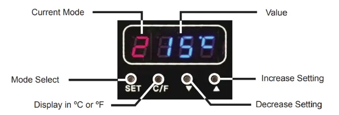
- Set the fan speed to level 10. Press the "Set" button until the “F” fan mode appears. Press the ▼ or ▲ buttons to adjust the fan setting to "10".
- Set the pump speed to level 10. Press the "Set" button until the “P” pump mode appears. Press the ▼ or ▲ buttons to adjust the pump setting to "10".
Figure 2: Heat Exchanger LED Display Panel
Operation
Use
- Power on the heat exchanger. The On/Off switch is located on the power adapter on the back of the heat exchanger.
Troubleshoot
Maintenance

