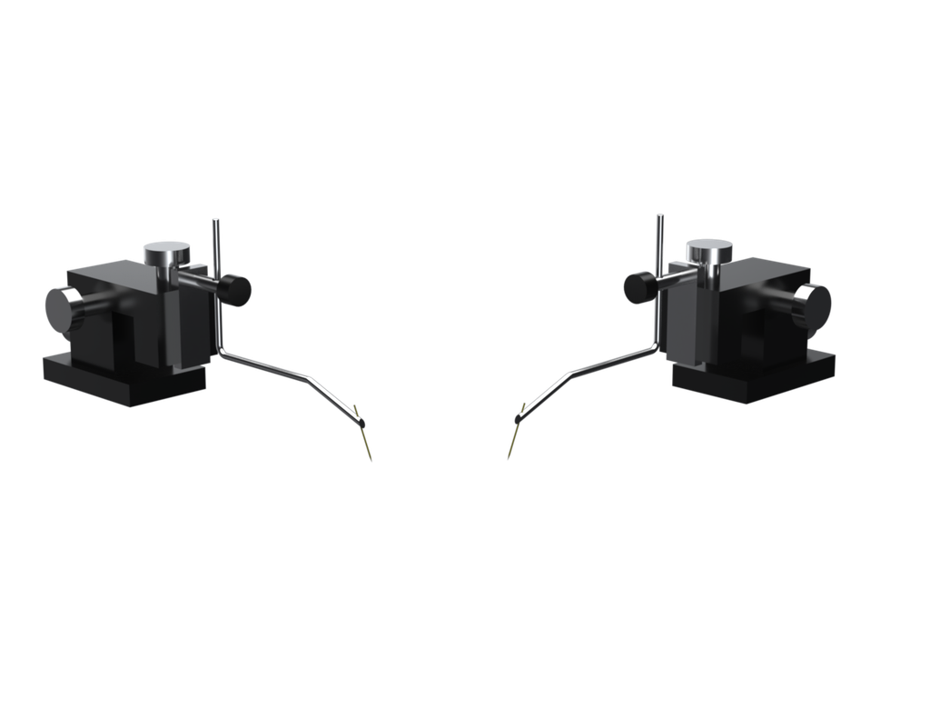
Device XYZ Needle Probe Set
PN0263 enables precise positioning of needle probes onto semiconductor pads. Each probe has a magnetic base and can be adjusted in the x, y, and z directions with +/- 7.5 mm movement along each axis. A wire lead with gold-plated contact pin is used to make electrical connection to the needle probe. Probes are offered in both left and right-hand versions. The right-hand version is shown.
Applications
-
Probe semiconductor die pads
-
Probe semiconductor package leads
-
Probe small circuit board components leads, pads, vias
Overview
Included Components
-
Device XYZ needle probe set, +/- 7.5 mm travel, magnetic base, right and left handed
-
[PN0463] Probe Needles, Gold Plated, 0.5 x 19mm, Set of 10
Included In
Required Products
Related Products
Manufacturer Information
Specifications
Needle Length |
12.5 mm |
Travel |
± 7.5 mm |
Dimensions | 38 mm W x 62 mm D x 45 mm H |
Setup
Installation
-
Insert a probe needle into the tip of the test arm so that the blunt end of the needle does not protrude above the test arm.
-
The test arm can swivel and be adjusted in the z direction using a thumbscrew (see Figure 1).
-
The needle probe position on the test arm can also be adjusted using a thumbscrew (see Figure 2).
Figure 1: Test arm thumbscrew
Figure 2: Needle probe thumbscrew
Operation
Use the three thumbscrews to position the probe arm:
Lens Damage: Microscopic lenses have short working distances and caution should be used when lowering the camera to prevent contacting the lens with the probe needles to avoid damage to the lens and anti-reflective coating.
-
Rotate the top screw clockwise from above to move up and counterclockwise to move down (see Figure 3).
-
Rotate the side screw clockwise to move forward and counterclockwise to move back (see Figure 4).
-
Rotate the back screw clockwise to move right and counterclockwise to move left (see Figure 5).
Figure 3: Top thumbscrew
Figure 4: Side thumbscrew
Figure 5: Back thumbscrew
Troubleshoot
Maintenance