Linear Stage Motor Controllers
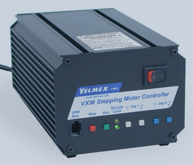
PN0187 and PN0304 enable control of 1-2 linear stages. The controller interface provides Jog buttons for each axis to manually position the stages.
Applications
-
Linear stage positioning
Overview
Included Components
- Power Supply
- RS232 Serial Cable, 6ft
Included In
Required Products
Related Products
Manufacturer Information
Specifications
| Weight (with power supply) | 3.9 lbs (1.77kg) |
| Dimensions | 3.52" X 4.37" X 6.89" (89.4 mm X 111 mm X 175 mm) |
| Interface |
RS-232 (serial port) |
| AC Power Supply |
100-240VAC 2A 50-60Hz |
| Controller Power |
24VDC 2.5A |
Setup
Installing the Automated Controller
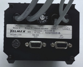
- Connect the thicker cable from the back of the controller labeled “Motor 1” to the corresponding six-position connector marked "1" on the stepper motor of the linear stage.
- Connect the thinner cable from the back of the controller labeled “Limits 1” to the corresponding four-position connector marked "1" near the top of the stage.
- (If Applicable) Repeat steps 1 and 2 for "Motor 2" and "Limits 2" cables.
- Connect the 9 pin RS-232 serial cable to the "Serial RS-232" port and a COM port of the PC. Repeat for the second controller (if applicable).
- Plug the 24VDC power supply cord into the back of the controller and then plug the power supply into a grounded 100-240 VAC outlet.
Figure 1: Motor controller back
Operation
Operating the Automated Stage
-
Use Jog the buttons on the front of the controller to adjust the camera height.
-
Press the + or - Jog button briefly to index the stepper motor in one step increments.
-
Press and hold a Jog button to adjust camera position more rapidly.
Figure 1: Motor controller front
- Use Jog the buttons on the front of the controller to adjust the camera height.
- Press the + or - Jog button briefly to index the stepper motor in one step increments.
- Press and hold a Jog button to adjust camera position more rapidly.
Figure 1: Motor controller front
Troubleshoot
Note: If the controller stops responding and the green LED light is not illuminated, press the circuit breaker button on the back of the controller to reset the breaker.
Maintenance

