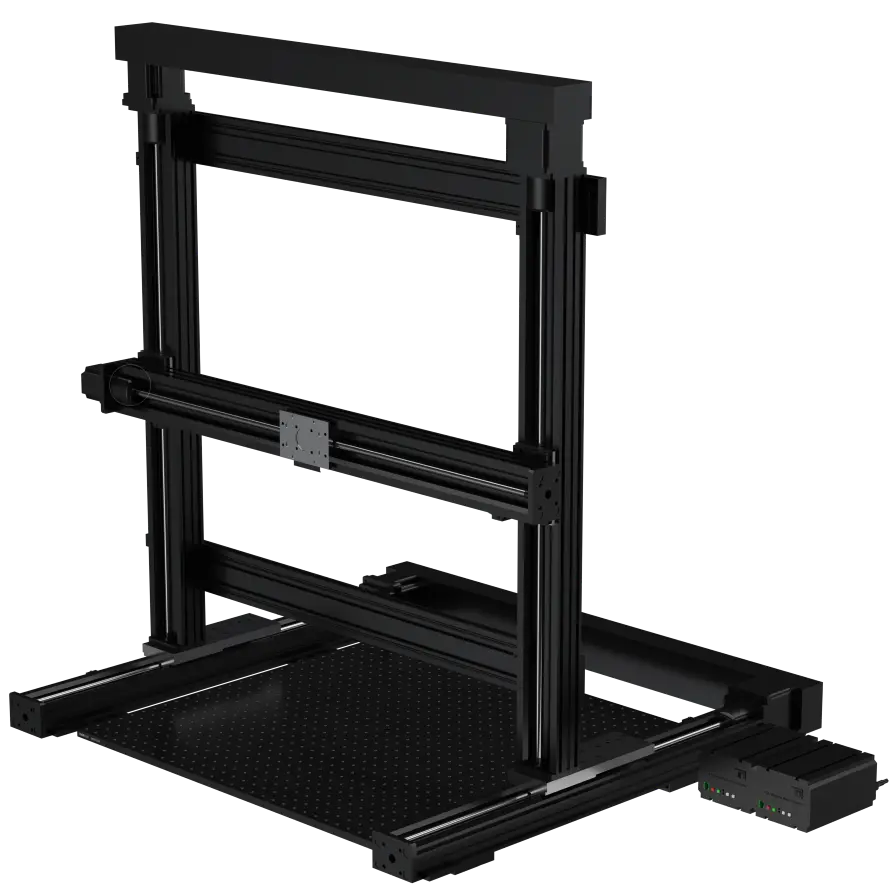
Camera Positioning System Auto XYZ 750
PN0410 enables fine positioning of a thermal camera. Motorized X, Y and Z stages enable homing and the ability to reposition the cameras automatically to known precise positions. Manual Z camera stages enable fine focusing and matching thermal and probing camera working distance.
Applications
-
Large semiconductor device failure analysis
-
Large circuit board failure analysis
Overview
Included Components
- [PN0097] ESD Mat, 750 x 500mm
-
[PN0411] Mounting Table 750
-
[PN0190] Linear Stages Auto XYZ 330 x 500mm
- [PN0333] Sentris Toolbox
- [PN0397] Linear Stage Motor Controller 4 Axis
-
[PN0614] Motor Controller Safety Kit
Required Products
Related Products
- [PN0314] Camera Positioning System Manual Z 450
-
[PN0250] Camera Positioning System Auto XYZ 600
- [PN0267] Camera Positioning System Manual Z 600
- [PN0303] Camera Positioning System Auto Z 600
- [PN0292] Camera Positioning Arm Manual XY
- [PN0480] Camera Positioning System Auto XYZ Desktop
Manufacturer Information
Specifications
Operation
Use
Camera position is controlled using the joystick or jog buttons on the linear stage controllers. Limit switches positioned at the ends of each stage axis to prevent overtravel and damage to the camera and lens.
Linear Stage Controllers
The XYZ Linear Stages are powered by turning on the power switches to both stage controllers (see Figure 1).
Controller Power: When turning on power to the controllers, do not move the joystick. If moved during power up, the center position of the joystick will not be initialized properly and one of the stages may advance without moving the joystick.

Figure 1: Linear Stage controller
Controlling Camera Position
Camera position is controlled using the joystick or jog buttons on the controllers.
Stage Operation: When operating the linear stages, pay close attention to obstructions (such as test devices, fixtures and leads) that may impede stage or camera/lens movement. The powerful stepper motors and fine lead screw pitch enable the carriages to move with great force. Any obstacles that impede carriage movement may be damaged or may damage the stage or camera/lens.
Motor Controller Jog Remote Operation
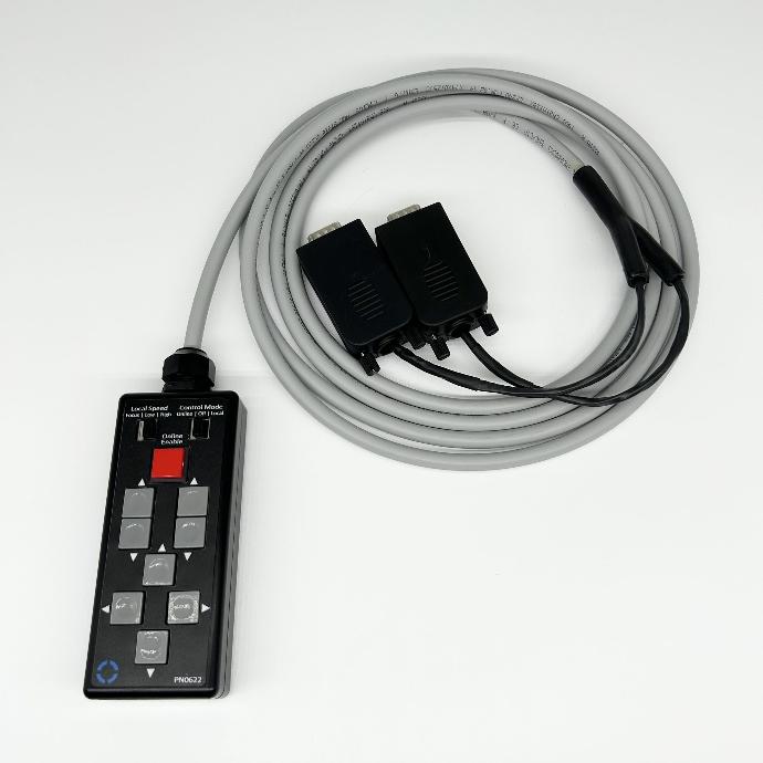
Figure 2: Motor Controller Jog Remote
Jog Buttons
The stage can also be controlled using the jog buttons on the front of the controllers.
Stage Limit switches
Limit switches are positioned at the ends of each stage axis to prevent over-travel and damage to the camera and lens. The lower limit switch of the Z stage has been removed and repositioned above the Fine Adjustment Focusing Stage (see Figure 3). The fine vertical focusing stage is spring loaded. If the camera or lens contacts an obstacle when lowered, the focusing stage will move upward (approximately 10 mm) and then activate the limit switch and stop the Z axis movement to prevent damage to the camera or lens.
Stage Operation: When moving the XYZ Camera Stage, do not rely on limit switches (especially the lower Z stage limit switch) to prevent damage when obstructions interfere with stage or camera/lens movement. Always pay close attention to potential obstacles when operating the stage.

Figure 3: Limit switch
XYZ Camera Stage Interlock (future feature)
When operating the stage using the joystick or jog buttons, the stage can be operated safely when the doors are open due to the slow speed of the slides and since operator action is always required to move the stage. A planned future feature is software control to command the stage to home itself and place the camera in repeatable positions. Software control will require all doors to be closed during operation and therefore the stage controllers will need to be integrated with the Enclosure Safety Interlock Circuit. This circuitry hardware is included but is not connected. When this feature is available, instructions for making required circuitry hardware connections will be provided.
Troubleshoot