High Frequency Relays
PN0266
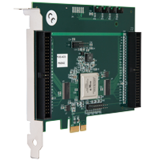
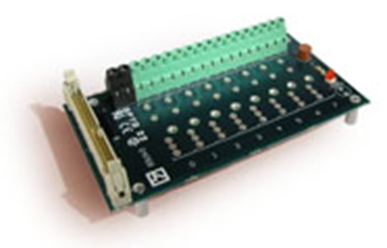
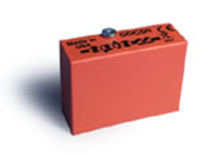
The Opto 22 PCIe-AC5 I/O card, G4PB8 mounting rack, and G4 ODC5R reed relay modules (see Figures 1, 2, and 3) are used to control voltage to electronic devices in high frequency and low current applications, such as failure analysis of packaged and bare semiconductor devices using Lock-in Thermography testing. A voltage source (not included), such as a source meter or power supply, is required to supply voltage to a device through one or more relays.
Applications
-
Lock-in Thermography testing of semiconductor devices (bare and packaged)
Overview
Relay outputs can also be used to trigger external test equipment. The maximum on/off frequency at which High Frequency Relays can be cycled is 15Hz. Unlike solid-state relays, reed relays have zero leakage current in the off state which is advantages when performing Lock-in Thermography tests on devices with low leakage current.
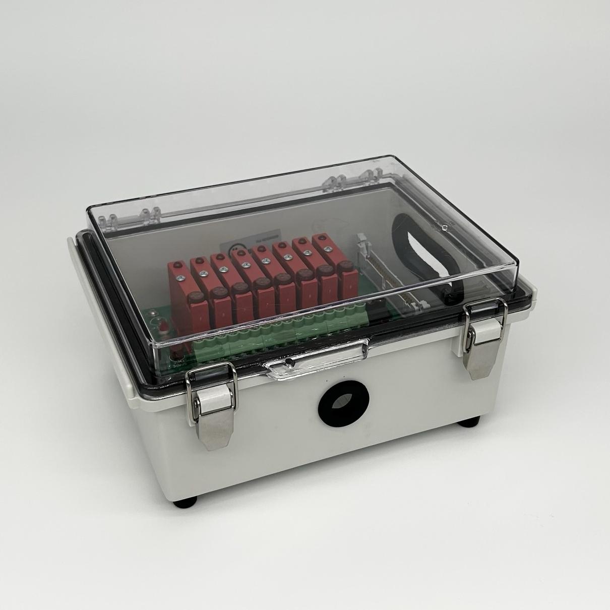
The rack can accommodate eight (8) Form A (SPST) reed relay modules. Maximum current is 0.5 Amp @ 20VDC and 20VAC. For voltages above 20VDC and 20VAC, the maximum current is determined by the following equation: Maximum Current = 10VA / Voltage. The rack 5VDC power supply requires 100-240 VAC, 50/60 Hz.
The module rack is mounted in a polycarbonate enclosure with clear cover. The enclosure is UL508/NEMA Type 4X with IP-67 TUV rating and UL-94 5VA rating. The enclosure has rubber access holes for the installing the flat ribbon cable and relay terminal leads and is powered by a 5VDC 2A power supply.
Status Indicators: A red LED on the top of each relay module indicates relay status (closed or open). An illuminated LED indicates that the relay is closed.
Included Components
-
Module rack (8 space)
-
Enclosure
-
Relay modules: 100 VDC max, 0.5 A max, >20V 10VA max, set of 8
-
Power supply (110-220 VAC, 50/60 Hz)
-
PCIe interface board
Figure 1: Reed relay card
Figure 2: Reed relay rack
Figure 3: Reed relay module
Required Products
Related Products
Manufacturer Information
Specifications
Opto22 ODC5R Reed Relay Module
| Contact type |
Form A SPST-normally open |
| Line Voltage - Range |
0–100 VDC 0–130 VAC |
| Current Rating * |
0.5 Amps Switching |
| Contact Rating * |
10 VA |
| Switching current |
0.5 amperes maximum |
| Carry current |
1.5 amps maximum |
| Contact on-resistance |
200 milliohms |
| Turn-on time |
500 microseconds |
| Turn-off time |
500 microseconds |
| Contact bounce |
250 microseconds |
| Mechanical life |
5 x 10⁶ cycles |
| Logic voltage range |
4.8–6 volts |
| Logic dropout voltage |
0.8 volts |
| Logic input current @ Normal logic voltage |
14 milliamperes |
| Isolation voltage Input-to-output |
1500 volts DC |
| Temperature Operating |
0 to 70 °C |
| Agency Approvals |
UL, RoHS, CE; UKCA |
Setup
Installation
Follow the procedure below to install the Opto 22 PCIe-AC5 I/O card, G4PB8 mounting rack, and G4 ODC5R reed relays. This will require installing hardware, software, and device drivers.
Preinstall: If you purchased the computer from Optotherm, all of the hardware, software, and drivers have been preinstalled on the computer. The information in this section is required only when updating software or if hardware drivers or software applications needs to be reinstalled.
Hardware Preinstall: The PCIe-AC5 card should be installed in the computer prior to installing the card drivers.
ESD Damage: Static electricity can damage the board. Before handling the board, ground yourself by touching the computer’s metal back panel.
I/O Card Installation
-
Shut down the computer and disconnect the computer power cord.
-
Remove the computer case cover.
-
Locate an available PCIe x1 (or larger) slot and remove the blank metal slot cover.
-
Push the ribbon cable through the slot and attach the cable to the 50-pin connector closest to the slot when the card is installed. Note: The two 50 pin connectors on the cable are not identical. Attach the cable connector that will allow the cable to exit directly through the slot and NOT double back.
-
Gently insert the I/O card into the slot and make sure that the board is seated properly.
-
Replace the computer case cover.
-
Connect the computer power cord.
Shut down the computer and disconnect the computer power cord.
Remove the computer case cover.
Locate an available PCIe x1 (or larger) slot and remove the blank metal slot cover.
Push the ribbon cable through the slot and attach the cable to the 50-pin connector closest to the slot when the card is installed. Note: The two 50 pin connectors on the cable are not identical. Attach the cable connector that will allow the cable to exit directly through the slot and NOT double back.
Gently insert the I/O card into the slot and make sure that the board is seated properly.
Replace the computer case cover.
Connect the computer power cord.
I/O Card Software and Driver Installation
-
Close any applications that may be running.
-
Download Opto 22 Setup and unzip using the 7-Zip File Archiver utility.
-
Open the folder named Opto 22 Setup ver… and double-click PC_DIRECT_SDK_Rx.xx.exe.
-
If the “Setup” window opens displaying the message “For legacy ISA AC5 users (XP only)…”, click [Ok].
-
On the “Setup – Opto 22 PC-Based Direct I/O SDK License Agreement” window, select “I accept the agreement” and click [Next].
-
On the “Select Destination Location” screen, click [Next].
-
On the “Ready to Install” screen, click [Install].
-
When the “Welcome to the Device Driver Installation Wizard!” window opens, click [Next].
-
When the “Completing the Device Driver Installation Wizard” window opens, click [Finish].
-
On the “Completing the Opto 22 PC – Based Direct I/O SDK Setup Wizard”, uncheck “Launch Direct Scan.exe” and click [Finish].
-
You may need to restart your computer for the I/O card to be recognized.
Close any applications that may be running.
Download Opto 22 Setup and unzip using the 7-Zip File Archiver utility.
Open the folder named Opto 22 Setup ver… and double-click PC_DIRECT_SDK_Rx.xx.exe.
If the “Setup” window opens displaying the message “For legacy ISA AC5 users (XP only)…”, click [Ok].
On the “Setup – Opto 22 PC-Based Direct I/O SDK License Agreement” window, select “I accept the agreement” and click [Next].
On the “Select Destination Location” screen, click [Next].
On the “Ready to Install” screen, click [Install].
When the “Welcome to the Device Driver Installation Wizard!” window opens, click [Next].
When the “Completing the Device Driver Installation Wizard” window opens, click [Finish].
On the “Completing the Opto 22 PC – Based Direct I/O SDK Setup Wizard”, uncheck “Launch Direct Scan.exe” and click [Finish].
You may need to restart your computer for the I/O card to be recognized.
Relay Setup
-
Insert the free end of the flat ribbon cable (the opposite end is connected to the PCIe I/O card installed in the computer) through the oval rubber grommet on the side of the relay enclosure and connect it to the 50-pin connector on the G4PB8 mounting rack.
-
Install the G4 ODC5R reed relay modules onto the rack by carefully aligning the module pins with the rack holes. Secure the modules by tightening the locking screw.
-
Insert the barrel plug of the 5VDC power supply into the jack on the side of the relay enclosure and then plug the power supply cord into a grounded outlet.
Operation
Relay Terminals
Screw Terminals
The G4PB8 mounting rack has 1 row of 18 screw terminals (see Figure 1) that are connected to eight relays (Form A SPST-normally open). Terminals 1 and 2 are connected to the first relay, terminals 3 and 4 are connected to the second relay, etc.
Default Relay State: At power-up, the relays are put into a non-energized state.

Figure 1: G4PB8 mounting
Inductive Loads
If you are using the relays to control inductive loads, place a diode across the load terminals to suppress the kickback voltage. If the diode is not present, the kickback voltage could cause the on-board processor to enter an unstable state. To return the processor to a stable state, unplug the power cable from the relay enclosure and then reconnect. A contact protection circuit is shown in Figure 2. For AC loads, install a metal oxide varistor (MOV).
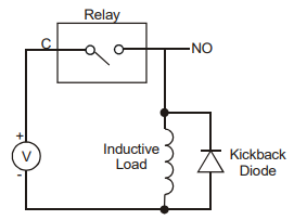
Figure 2: Inductive load protection circuit
Electrical Connections
When performing Lock-in Thermography, Model Comparison, or Image Sequence tests, voltage is controlled to an electronic device using one or more relays. A set of test leads is included with your relay device for making electrical connections to electronic package pins or to probe needle positioners. Electronic package test leads include spring clips that attach to package pins. Probe needle positioner test leads are terminated with male spring pins that insert into the probe positioners.
The following example shows how to connect the spring clips to device pins, High Frequency Relays, and a voltage source (see Figure 3).
-
Connect the red banana jack to the positive (+) terminal on the voltage source.
-
Insert the opposite end of the red banana jack test lead into an odd numbered screw terminal (e.g., 1) and then tighten the terminal screw.
-
Connect the red spring clip to the appropriate package pin.
-
Insert the opposite end of the red spring clip lead into the adjacent, higher-numbered (e.g., 2) screw terminal and tighten.
-
Connect the black banana jack to the negative (-) terminal on the power source.
-
Connect the black spring clip to the appropriate package pin.
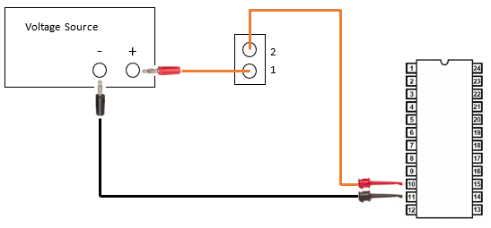
Figure 3: Relay electrical connections using electronic package test leads
Overcurrent Damage
The current limiting function of a voltage source is typically employed to prevent damage to electronic devices during testing. When the current limit is reached, the voltage source automatically reduces voltage until the current limit is no longer exceeded. All voltage sources, however, require time (specified by slew rate) to reduce output voltage when limiting current. Slew rate is typically very short and is usually measured in microseconds. During this time however, there is a chance that higher current than expected may flow through the relay and device, resulting in relay and/or device damage. The slew rate of source meters is typically much faster than power supplies. Therefore, relay damage is less likely when using a source meter.
If a relay is damaged by overcurrent, there may be no clear signs of damage, but it may not close and/or open properly. When testing a device, if your voltage source output does not match the expected output, this may be a sign of relay damage. In this case, replace the relay fuse or try using a different relay. A relay can be tested by replacing the test device with a resistor (such as 1 kohm) and setting the voltage source to a low voltage (such as 1 V). Enable the voltage source output and verify that the output current cycles between 0 and the expected current (1mA in this case).
Troubleshoot
PCIe-AC5 Not Detected
Symptoms
When PCIe-AC5 is selected in one of the Relay Setup windows and then the Initialize Selected Device button is clicked, a message is displayed indicating that the device was not detected.
Solution 1: If the PCIe-AC5 I/O card has not been installed, close Thermalyze, install the card according to instructions in the Optotherm Sentris System Software Installation Manual, and then restart Thermalyze. If the problem continues, proceed to the next solution.
Solution 1: Uninstall and then reinstall the PCIe-AC5 I/O card software and drivers according to the following procedure:
-
Close Thermalyze.
-
Open the Windows Apps & Features window and uninstall Opto 22 PC-Based Direct I/O SDK version Rx.xx.
-
Reinstall the I/O Card Software and Driver Installation according to instructions in the Optotherm Sentris System Software Installation Manual.
-
Restart Thermalyze.
Maintenance
