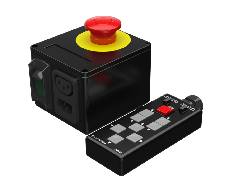
Motor Controller Safety Kit
PN0614 contains an emergency stop button and motor controller jog remote with both local and online control.
Applications
- Linear stage safety
Overview
Included Components
- [PN0567] Emergency Stop Box
- [PN0622] Motor Controller Jog Remote
- C13-C14 cable
- C14-C13 splitter cable
-
Mounting hardware and tools
Included In
Required Products
Related Products
Manufacturer Information
Specifications
Setup
[PN0567] Emergency Stop Box
- Connect the C13-C14 power cable to the lower C13 connector on PN0567. Connect the C14 end to the PDU (if applicable) or a 110-240VAC grounded power outlet.
- Connect the C14-C13 splitter cable to the upper C14 connector on PN0567. Connect the split C13 ends to the motor controller power supplies (or another device that is to be controlled).
- Toggle the circuit breaker switch to the on position.
- Ensure red button is in the extended position by twisting it in the direction of the arrows.
Figure 1: [PN0567] back
[PN0622] Motor Controller Jog Remote
- Plug in the serial connectors to their corresponding controller and tighten the thumb screws.
- Switch the Control Mode switch to Online if you are operating the linear stages through the linear stage window in Thermalyze. Switch the Control Mode switch to Local if you are operating the linear stages with the Jog Remote buttons. See Figure 2.
- When set to Local, the Local Speed switch can be set to Focus, Low, or High. This switch does not affect the linear stage speed when set to Online mode. See Figure 2.
Figure 2: [PN0622] zoomed
Operation
Note: Return the "Control Mode" is set to "Off" before turning on the motor controllers.
[PN0567] Emergency Stop Box
- Press the red button to stop linear stage operation.
- Reset red button by twisting in the clockwise direction until it extends to the out position.
[PN0622] Motor Controller Jog Remote
- When set to Online, push and hold the red Online Enable button while operating the linear stages with the linear stage window in Thermalyze. If the red button is released, the linear stages will stop. See Figure 2 above.
- When set to Local, the Local Speed can be set to Focus, Low, or High. Press the arrow buttons to move the stages along the X, Y, Z axes. Use Figures 3 and 4 below to see which axis each button set controls.
Figure 3: [PN0622] button diagram corresponding to controller (C1 or C2) and motor (M1 or M2)
Troubleshoot
Maintenance