Device Probing Camera Manual XYZ

PN0283

The primary use of the probing camera is to display small areas on electronic devices when making electrical connections using probes.  The camera can also be used to capture images of the unit under test for use with the Picture Overlay software tool.  See the Thermalyze HTML Help for detailed information about Picture Overlay.

Applications

Request a Quote

Overview

Specifications

Setup

Operation

Troubleshoot

Maintenance

    Overview

Camera

Sentris probing cameras are USB3 Vision compliant color digital camera with 1280 x 960 pixel resolution, image capture rate of 30 frames-per-second and is USB powered.

Lens

The Circuit Board Probing Lens is used to probe contact sites larger than 100 x 100 µm on both circuit boards and semiconductor devices (see Figure 1).  This lens provides zoom ratio of 10:1, with magnification from 0.023X to 0.82X and 150 mm minimum working distance.  Note: Closer working distances are possible but will prevent focusing on lower zoom levels.  The lens has manual focus, zoom, and aperture.  Thumbscrews allow the focus, zoom, and aperture rings to be locked in place if required.

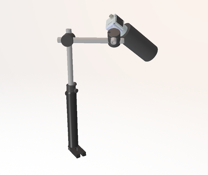
Figure 1: Circuit Board Probing Lens installed on the XY Probing Camera Arm

LED Spot Lights

The LED Spotlights provide cool, even lighting.  An adjustable dimmer knob controls the amount of light illuminating the target and each light can be precisely aimed with the 50 cm long dual goosenecks.

XY Probing Camera Arm

The XY Probing Camera Arm allows the probing camera to be manually positioned in any orientation when probing both circuit boards and semiconductor devices. The arm is very rigid with minimal sag and is comprised of aluminum joints with PTFE bearings, rubber-coated steel knobs, and steel threaded posts.  Needle bearing provide smooth adjustment of joint friction.  A ball swivel clamp with thumb screw enables a wide range of camera viewing angles.  The arm mounts on a rigid stainless steel 40 mm post and provides 500 mm reach and weighs 1.6 Kg.

Included Components

  • Video camera (color, 1294 x 964 pix, 30 fps, USB 3.0 Vision)

  • Zoom lens (40-80 mm working distance, min FOV 0.4 x 0.6mm)

  • Camera cable (USB 3.0, Micro B screw lock/A, 3 m)

  • Manual XYZ arm assembly with post and post mount

  • LED control box

  • LED power supply (85-265VAC/50-60 Hz)

  • Two (2) gooseneck spotlights

  • Mounting bracket

Required Products


Related Products 


Manufacturer Information


    Specifications


    Setup

Installation

LED Spotlights
  1. 1.Attach the mounting bracket to the platform using the two (2) M6 x 12 mm screws and washers provided.  See the Sentris Mounting Hardware User Manual for proper mounting position on the platform.

  2. Insert the gooseneck spotlight connectors into the top of the LED control box by aligning the notches on the connectors and then tighten the connectors securely.

  3. Plug the LED power supply into the LED control box and then into a power outlet.

Figure 1: LED Spotlights

    Operation

Lens

Adjusting Focus

To adjust the focus, make sure the focus thumbscrew is loose and then twist the focus ring (see Figure 1).  If the working distance is equal to or greater than 150 mm, then the lens can be focused at the full range of zoom levels.  Closer working distances are possible but will prevent focusing at lower zoom levels.  

Figure 1: Circuit Board Probing Lens

Setting the Zoom

The lens zoom has a range from 1X to 10X.  To adjust the zoom level, make sure the zoom thumbscrew is loose and then twist the zoom ring (see Figure 4.2.1).

Setting the Aperture

The lens aperture controls how much light enters the lens and determines the depth of focus.  Opening the aperture allows more light to enter but reduces the depth of focus.  Closing the aperture will darken the image but will increase depth of focus.  When the aperture is reduced, an additional light source may be required to illuminate the target and provide an image with sufficient contrast.

The appropriate aperture setting will depend on your specific application.  If you would like more of the target to be in focus, reduce the aperture and add more light if required.  To adjust the aperture, make sure the aperture thumbscrew is loose and then twist the aperture ring (see Figure 4.2.1).

Lens Setup Procedure
  1. 1.Set the zoom level to minimum zoom

  2. Position the camera so that the target is in view

  3. Setup the LED Lights (if included) to illuminate the target at full brightness

  4. Adjust focus

  5. Adjust the aperture to optimize scene contrast and depth of focus

  6. Set the zoom level

  7. Adjust focus

LED Spotlights
  1. 1.Bend the gooseneck spot lights into position by holding the base of the gooseneck (near the connector) with one hand and the spotlight with the other hand.  This will help prevent excessive strain on the mating connectors.

  2. Turn the dimmer knob to adjust the brightness.

  3. You may need to experiment with the position of the spotlights to minimize reflections and glare off the target into the probing camera.  Tip: Position the spotlights so that they illuminate the target from the front or side to reduce reflections and glare.

XY Probing Camera Arm

Adjusting Joint Stiffness

Rotate the joint knobs to set the stiffness of each joint.  Tightening a joint will decrease arm sag.  Adjust each joint so that the camera can be repositioned easily with minimal arm sag.

Changing Arm Height

Probing camera height can be raised or lowered by loosening the arm clamp knob and sliding the clamp up or down on the 40 mm post.  Tip: When raising or lowering the arm, support the center of the arm with one hand so that the clamp slides more smoothly on the post.

    Lens Damage: Support the probing camera or lens with your hand when loosening the ball swivel clamp to prevent the lens from swinging down and striking another object.

        Troubleshoot


        Maintenance

    See Lens Cleaning