![[PN0293]](/web/image/13097-834f6bf0/probing%20camera%20lens%20notch.png)
Device Probing Microscope Camera
PN0293 displays small areas on electronic devices when making electrical connections using probes. The camera can also be used to capture images of the unit under test for use with the Picture Overlay software tool.
Applications
-
Semiconductor device probing
Overview
Included Components
-
Video Camera
-
Microscopic Zoom Lens
-
Camera Cable
-
Ring light with lens mounting screws
-
LED control box
-
Mounting hardware
Required Products
Related Products
Manufacturer Information
Specifications
LED Control Box
| Voltage |
85-265VAC |
| Frequency | 50-60 Hz |
Microscopic Zoom Lens
| 0.5X objective |
Magnification from 0.3X (12 x 16 mm FOV) to 2.0X (1.6 x 2.4 mm FOV) with 175 mm working distance |
| 1X objective |
Magnification from 0.6X (6 x 8 mm FOV) to 4.0X (0.8 x 1.2 mm FOV) with 82 mm working distance |
| Zoom | Manual |
| Focus |
Adjust the height of the probing camera |
Probing Cameras - Common
Setup
Installation
Install Lens
-
Insert lens into the linear stage camera bracket. Gently tighten the thumb screw.
The thumb screw contains a ball plunger tip to allow camera rotation.
USB Cable Connection
Install LED Ring Light
-
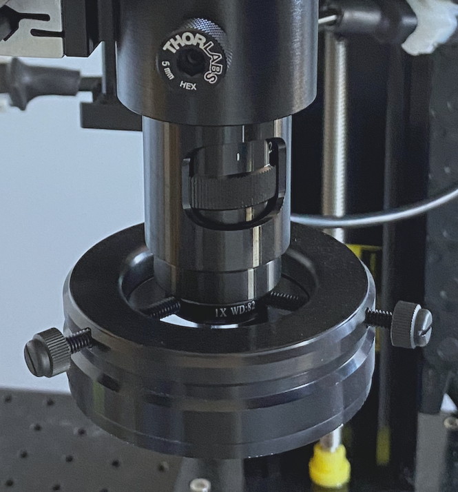
Loosen thumbscrews on the ring light and slip over the end of the Probing Zoom Lens (see Figure 1).
-
Make sure the thumbscrews align with the notch on the end of the lens and then tighten the thumbscrews.
-
Plug the LED control box into a power outlet.
Figure 1: Mount PN0293 LED ring light
Operation
LED Ring Light
-
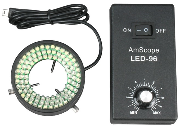
To illuminate targets when capturing probing camera images, an LED Ring Light (see Figure 2) is mounted on the end of the Probing Camera lens. The LED Ring Lights provide cool lighting and does not require positional adjustment as it is always aimed directly at the target. An adjustable dimmer knob controls the amount of light illuminating the target. Turn the dimmer knob to adjust the brightness.
Figure 2: LED Ring Light
Maintenance

