Cable Chain Installation
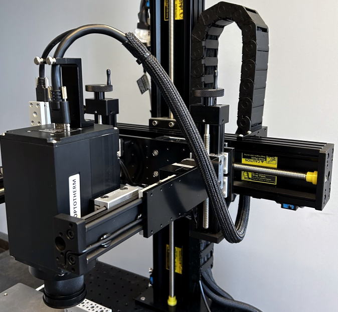
The cable chain organizes cables connected to system components that move with linear stage carriages.
Open a closed link by inserting a slotted screwdriver into the back side of the link and then twist to open.
Close an open link by pressing the link closed until it snaps.
-
Include the following items in the cable chain:
-
Cable sleeve containing the Infrasight camera and [PN0293] Device Probing Microscope Camera.
-
Cable sleeve containing the X stage motor and limit switch cables of [PN0251] Linear Stages Auto XZ 330x500.
-
Cable sleeve containing the Y stage motor and limit switch cables of [PN0403] Linear Stages Manual Z Auto Y 100 Left.
-
Cable sleeve containing the Y stage motor and limit switch cables of [PN0261] Linear Stages Manual Z Auto Y 100 Right.
-
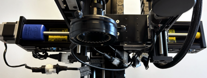
The LED Ring Light cord of [PN0293] Device Probing Microscope Camera.
-
-
Insert the cable sleeve, starting at the bottom of the chain, so that they follow the chain upward, through the U-turn, and exits the chain downward (see Figure 2).
-
To position cables in the chain while inserting additional cables, temporarily close the link at the top of the U-turn.
Cable Strain Test: After all cables have been inserted in the cable chain, linear stages must be tested slowly for full range of movement. If there is any cable strain or pinching, cable position must be adjusted in the cable chain.
Figure 1: IS640-17 cable sleeve
Figure 2: PN0403 Y stage cables, PN0261 Y stage cables, and PN0293 LED ring light cord

