High Current Relays (retired)
PN0167
The High Current Relays are used to control voltage and current to electronic devices in low frequency and high current applications, such as failure analysis of bare circuit boards to detect and locate power/ground short circuits using Lock-in Thermography testing. High Current Relays are also used when troubleshooting populated boards using Model Comparison testing. A voltage source (not included), such as a source meter or power supply, is required to supply voltage through one or more relays to the electronic device.
Relays can also be used to trigger external test equipment like functional testers to electrically energize circuit boards. The maximum on/off frequency at which High Current Relays can be cycled is 1Hz.
Populated circuit boards can be electrically exercised in different ways, depending on the type of board and the nature of the defect. For example, in no-fault-found conditions, circuit boards can be powered for normal boot-up. On the other hand, to isolate power-to-ground shorts, voltage can be applied to individual power rails. Or when in-circuit test identifies a short between nodes, the circuit containing the fault can be powered separately using probes are by soldering leads onto the board.
Applications
-
Lock-in Thermography testing of power-to-ground short circuits on populated circuit boards
-
Model Comparison testing of populated circuit boards
Overview
Included Components
-
High current, 6A, SPDT relays (qty 8)
-
Power Supply, 9VDC, 1.66A, 2.1x5.5mm ID
-
Relay Test Leads
-
USB 2.0
Required Products
Related Products
Manufacturer Information
Specifications
Switch & Sense 8/8 Form C SPDT relays
| Number |
8 |
| Contact configuration |
8 FORM C (SPDT) NO, NC and Common available at connector |
| Contact rating |
6 amperes (A) @ 120 volts AC (VAC) or 28 volts DC (VDC) resistive |
| Contact resistance |
100 milliohms (mohm) max |
| Operate time |
10 milliseconds(ms) max |
| Release time |
5 ms max |
| Vibration |
10 to 55 hertz (Hz) (Dual amplitude 1.5 millimeters (mm)) |
| Shock |
Shock 10 G (11 ms) |
| Dielectric isolation |
500 V (1 minute) |
| Life expectancy |
10 million mechanical operations min |
| Power on RESET state |
Not Energized, NC in contact to Common |
Setup
Installation
Follow the procedure below to install the Measurement Computing Switch & Sense 8/8 USB relays. This will require installing software, hardware, and device drivers and to configure the relays.
Preinstall: If you purchased the computer from Optotherm, all of the hardware, software, and drivers have been preinstalled on the computer. The information in this section is required only when updating software or if hardware drivers or software applications needs to be reinstalled.
Software Installation
-
Close any applications that may be running.
-
Download MccDaq Setup and unzip using the 7-Zip File Archiver utility.
-
Open the folder named MccDaq Setup ver… and double-click mccdaq.exe.
-
When the “WinZip Self-Extractor - mccdaq.exe” window opens, click [Setup].
-
On the “MCC DAQ” window, uncheck DAQami (make sure InstaCal & Universal Library is checked) and click [Install].
-
When the “InstaCal and Universal Library” window opens, click [Next].
-
On the “Destination Folder” screen, click [Next].
-
On the “InstaCal and Universal Library” screen, uncheck all Universal Library Examples, and then click [Next].
-
On the “Ready to Install the Program” screen, click [Install].
-
If the “Window Security” window opens, check “Always trust software from Measurement Computing Corporation”, and then click [Install].
-
On the “InstallShield Wizard Completed” screen, click [Finish].
-
If the “DASYLAB Software” window opens, click [No Thanks].
-
When prompted to restart the system, click [Yes].
Device Driver Installation
-
Connect the power supply to the relay box and to a power outlet. The green LED on the back of the relay box labeled “External Power” will illuminate.
-
While the computer is running, plug the relay box USB cable into an available USB port on the computer.
-
The “USB Input Device” popup balloon will open and then close automatically.
Relay Configuration
-
Click [Start] on the Windows taskbar, then [Measurement Computing], then [InstaCal] to open the “InstaCal” window.
-
If the “System Modifications Required” window opens, click [Yes] and continue with step 3. If this window does not open, proceed to step 6.
-
When the “HID Registry Updater” window opens, click [Update].
-
When prompted, cycle power to the relay box and then close the window.
-
Repeat step 1 to run InstaCal.
-
When the “Plug and Play Board Detection” window opens, click [OK].
-
Close the “InstaCal” window.
Figure 1: Switch & Sense 8/8
Operation
Relay Terminals
Screw Terminals
-
The Switch & Sense 8/8 has four rows of screw terminals (see Figure 1) - two outer rows containing 12 terminals each and two inner rows containing eight terminals each.
-
The outer rows of terminals connect to the eight relays.
-
The inner rows connect to the differential isolated digital inputs (not used).
Default Relay State: At power-up, the relays are put into a non-energized state (NC in contact to Common).

Figure 1: Switch & Sense 8/8 screw terminals
Relay Contact Terminals

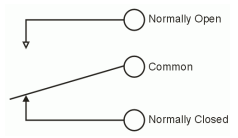
Figure 2: Form C SPDT relay
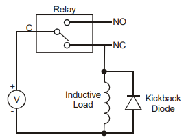
Inductive Loads

Figure 3: Inductive load protection circuit
Electrical Connections
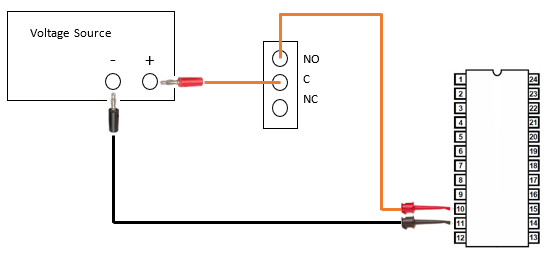
The following example shows how to connect the spring clips to device pins, High Current Relays, and a voltage source (see Figure 4).
Connect the red banana jack to the positive (+) terminal on the voltage source.
Insert the opposite end of the red banana jack test lead into the Common (C) screw terminal of one of the relays and then tighten the terminal screw.
Connect the red spring clip to the appropriate package pin.
Insert the opposite end of the red spring clip lead into the Normally Open (NO) screw terminal of the same relay used in step 2 and tighten.
Connect the black banana jack to the negative (-) terminal on the power source.
Connect the black spring clip to the appropriate package pin.

Figure 4: Relay electrical connections using electronic package test leads
Status Indicators
| LED Illumination | Indication |
| Steady green | The Switch & Sense 8/8 is connected to a computer or external USB hub |
| Blinks continuously | Data is being transferred |
| Blinks continuously | Initial communication is established between the Switch & Sense 8/8 and the computer |
Troubleshoot
Switch & Sense 8/8 Not Detected
Symptom
When Switch & Sense 8/8 is selected in one of the Relay Setup windows and then the Initialize Selected Device button is clicked, a message is displayed indicating that the device was not detected.
-
Select Windows start >> Measurement Computing >> Instacal.
-
In the Instacal window, select the relay device and remove it by clicking the X button.
-
Unplug the relay USB cord from the computer, cycle power to the relay box, and then plug the USB cord back into the computer.
-
In the Instacal window, click Refresh Boards. There should see an indication that the relay device was detected.
-
Close Instacal.
Solution 1: Make sure the High Current Relays are powered and connected to a computer USB port. If the problem continues, proceed to the next solution.
Solution 1: Close and restart Thermalyze. If the problem continues, proceed to the next solution.
Solution 1: If the Switch & Sense 8/8 has not been installed, close Thermalyze, install the device according to instructions in the Optotherm Sentris System Software Installation Manual, and then restart Thermalyze. If the problem continues, proceed to the next solution.
Solution 1: Restart the computer. If the problem continues, proceed to the next solution.
Solution 1: Reconfigure the relays by following this procedure:
-
Select Windows start >> Measurement Computing >> Instacal.
-
In the Instacal window, select the relay device and remove it by clicking the X button.
-
Unplug the relay USB cord from the computer, cycle power to the relay box, and then plug the USB cord back into the computer.
-
In the Instacal window, click Refresh Boards. There should see an indication that the relay device was detected.
-
Close Instacal.
Maintenance
